Nissan Rogue (T33) 2021-Present Service Manual: Component Parts
With 8" Color Display
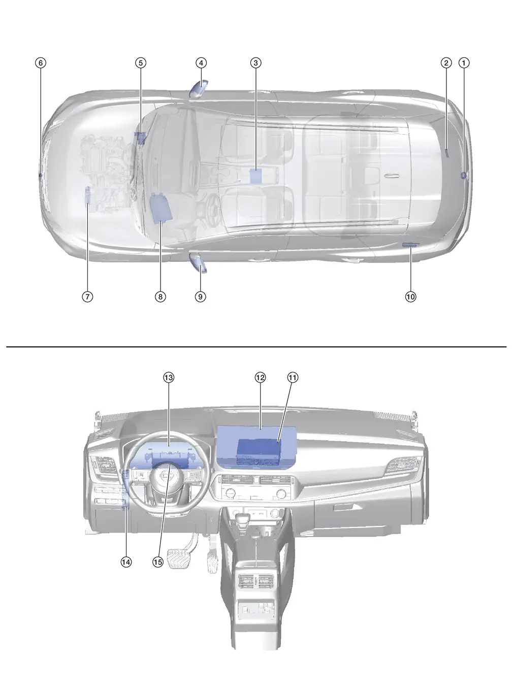
Component Parts Location
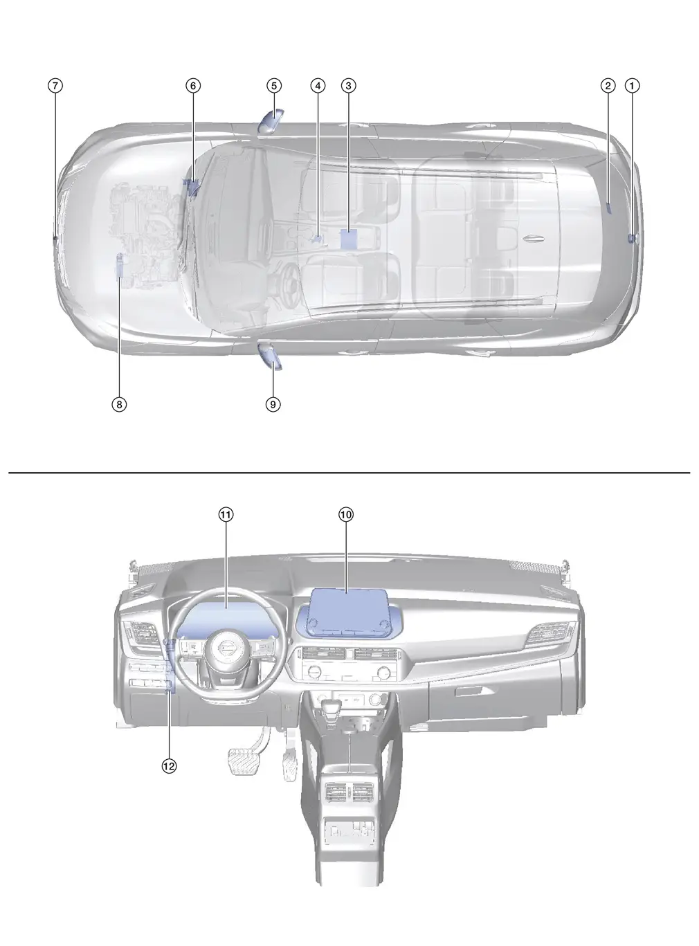
| No. | Component | Function |
|---|---|---|
| 1. | Rear camera | Refer to Rear Camera. |
| 2. | Sonar control unit | Provides the around view monitor control unit with the sonar indicator signal via CAN communication. |
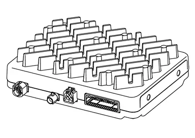
| 3. | Around view monitor control unit | Refer to Around View Monitor Control Unit. |
| 4. | Drive mode switch (AWD) | Refer to Drive Mode Select Switch. |
| 5. | Side camera RH | Refer to Side Camera. |
| 6. | ABS (Anti-lock Braking System) actuator and electric unit (control unit) |
Provides the around view monitor control unit with the following signals via CAN communication:
|
| 7. | Front camera | Refer to Front Camera. |
| 8. | TCM (Transmission Control Module) | Provides the around view monitor control unit with the shift position signal via CAN communication. |
| 9. | Side camera LH | Refer to Side Camera. |
| 10. | AV control unit |
Provides the around view monitor control unit with the following signals via CAN communication:
|
| 11. | Combination meter | Provides the around view monitor control unit with the MOD setting signal via CAN communication. |
| 12. | BCM (Body Control Module) |
Provides the around view monitor control unit with the following signals via CAN communication:
|
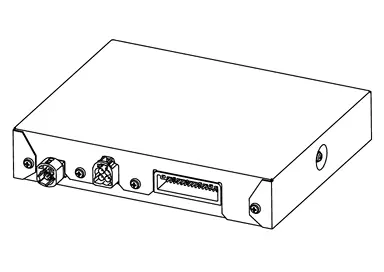
Around View Monitor Control Unit
-
Around view monitor control unit is located under the center console.
-
Camera image signals received from each camera are converted/synthesized in the around view monitor control unit and transmitted to the AV control unit by LVDS.
 NOTE:
NOTE:
LVDS (Low Voltage Differential Signaling): LVDS is a differential signaling system, transmitting information as the difference of voltages on a pair of wires. The two wire voltages are compared at the receiver.
-
Supplies power to each camera.
-
Signals necessary for operation are transmitted/received to/from the around view monitor control unit via CAN communication.
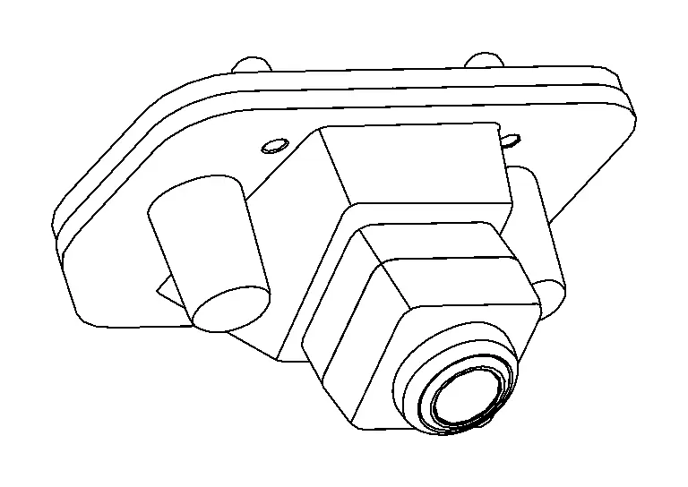
Front Camera
-
Front camera is installed in the front grille.
-
Power for the camera is supplied from the around view monitor control unit, and the image at the front of the Nissan Ariya vehicle is sent to the around view monitor control unit.
Side Camera
-
Side camera is installed in the left and right door mirrors.

-
Power for the camera is supplied from the around view monitor control unit, and the image at the side of the Nissan Ariya vehicle is sent to the around view monitor control unit.
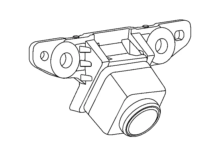
Rear Camera
-
Rear camera is installed in the center of the back door.
-
Power for the camera is supplied from the around view monitor control unit, and the image at the rear of the Nissan Ariya vehicle is sent to the around view monitor control unit.
With 12.3" Color Display
Component Parts Location
| No. | Component | Function |
|---|---|---|
| 1. | Rear camera | Refer to Rear Camera. |
| 2. | Sonar control unit | Provides the around view monitor control unit with the sonar indicator signal via CAN communication. |
| 3. | Around view monitor control unit | Refer to Around View Monitor Control Unit. |
| 4. | Side camera RH | Refer to Side Camera. |
| 5. | ABS (Anti-lock Braking System) actuator and electric unit (control unit) |
Provides the around view monitor control unit with the following signals via CAN communication:
|
| 6. | Front camera | Refer to Front Camera. |
| 7. | TCM (Transmission Control Module) | Provides the around view monitor control unit with the shift position signal via CAN communication. |
| 8. | Head up display | Refer to Head Up Display Unit. |
| 9. | Side camera LH | Refer to Side Camera. |
| 10. | HD navigation unit | Refer to Component Parts Location. |
| 11. | AV control unit |
Provides the around view monitor control unit with the following signals via CAN communication:
|
| 12. | Display unit | Refer to Display Unit. |
| 13. | Combination meter | Provides the around view monitor control unit with the MOD setting signal via CAN communication. |
| 14. | BCM (Body Control Module) |
Provides the around view monitor control unit with the following signals via CAN communication:
|
| 13. | 8CH CAN gateway | Provides routing for the AV communication, CAN communication and ethernet communication signals. |
Around View Monitor Control Unit
-
Around view monitor control unit is located under the center console.
With 3D Fixed View

With 3D Full 360 Degree View
-
Camera image signals received from each camera are converted/synthesized in the around view monitor control unit and transmitted to the AV control unit by digital signal.
-
Supplies power to each camera.
-
Signals necessary for operation are transmitted/received to/from the around view monitor control unit via CAN communication.
Front Camera
-
Front camera is installed in the front grille.
-
Power for the camera is supplied from the around view monitor control unit, and the image at the front of the Nissan Ariya vehicle is sent to the around view monitor control unit.
Side Camera
-
Side camera is installed in the left and right door mirrors.
-
Power for the camera is supplied from the around view monitor control unit, and the image at the side of the Nissan Ariya vehicle is sent to the around view monitor control unit.
Rear Camera
-
Rear camera is installed in the center of the back door.
-
Power for the camera is supplied from the around view monitor control unit, and the image at the rear of the Nissan Ariya vehicle is sent to the around view monitor control unit.
Other materials:
Component Parts
Propilot Assist 1.1
Component Parts Location
No. Component Function
1.
Front camera unit
Refer to Component Parts Location for detailed component location.
2.
AV control unit
Refer to Component Parts Location for detailed component location.
3.
Chassis control modu ...
Removal and Installation. Road Wheel Tire Assembly
Exploded View
Tire assembly
: N·m (kg-m, ft-lb)
Removal & Installation
REMOVALRemove wheel nuts.
Remove tire assembly.INSTALLATIONNote the following, install in the reverse order of removal.
When replacing or rotating wheels, perform following;
Perform the ID regist ...
Dtc/circuit Diagnosis. Power Supply and Ground Circuit
Moonroof Motor Assembly
Diagnosis Procedure
CHECK FUSE
Ignition switch OFF.
Check that the following fuse is not blown (open):
Fuse No. Capacity
31
15 A
Is the fuse blown (open)?
YES>>
Repair the blown (open) fuse after repairing the affected circuit if a fuse ...