Nissan Rogue (T33) 2021-Present OwnerŌĆÖs Manual & User Guide: Basic information
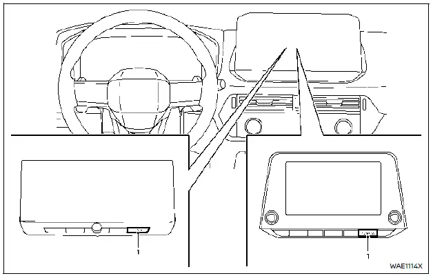
- CAMERA button
WARNING
- Failure to follow the warnings and instructions for proper use of the Moving Object Detection (MOD) system could result in serious injury or death.
- The MOD system is not a replacement for safe driving practices. Always check surroundings with mirrors and direct observation to ensure it is safe to maneuver your Nissan Rogue.
- The MOD system is disabled above 5 MPH (8 km/h) and reactivates at lower speeds.
- The MOD system does not detect stationary surrounding objects.
The MOD system alerts the driver to moving objects around the Nissan Rogue when maneuvering in areas such as garages, parking lots, or tight spaces.
The system detects motion by processing images from the vehicleŌĆÖs cameras and highlights movement on the display.
MOD system operation (models without 3D view)
The MOD system activates automatically under the following conditions:
- Shift lever in R (Reverse).
- CAMERA button pressed to activate the Intelligent Around View Monitor.
- Vehicle speed drops below 5 MPH (8 km/h).
The MOD system operates in these situations when a camera view is shown:
- With the shift lever in P (Park) or N (Neutral) and the vehicle stopped, the system detects movement in the birdŌĆÖs-eye view.
The MOD system will not work if a door is open. If the outside mirrors are folded, MOD performance may be reduced. - With the shift lever in D (Drive) and speed below 5 MPH (8 km/h), MOD detects movement in the front or front-wide view.
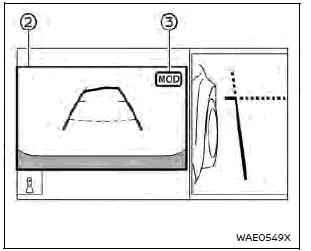
- With the shift lever in R (Reverse) and speed below 5 MPH (8 km/h), MOD detects movement in the rear or rear-wide view. The system will not operate if the liftgate is open.
The MOD system does not detect motion in the front-side or rear-side views (if equipped). No MOD icon will be shown in those views.
When the MOD system detects a moving object, a yellow frame appears on the corresponding area of the display and a single chime sounds. If movement continues, the yellow frame remains visible.
NOTE:
While the RCTA (Rear Cross Traffic Alert) chime is sounding, the MOD system will not chime.
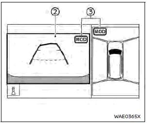
Front and bird's-eye views
Front and front-side views (example)
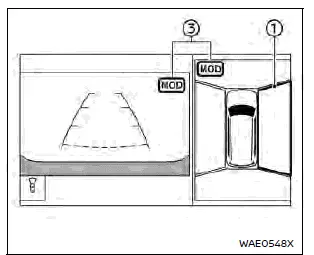
Rear and bird's-eye views
Rear and front-side views
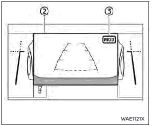
Front-wide view / rear-wide view
In birdŌĆÖs-eye view, the yellow frame 1 highlights the area (front, rear, left, right) where moving objects are detected.
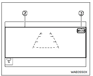
The yellow frame 2 appears in the front, rear, front-wide, and rear-wide views when movement is detected.
A green MOD icon 3 is shown in the view where the MOD system is active.
A gray MOD icon 3 appears in the view where the system is available but not active.
If the MOD system is turned OFF, the MOD icon 3 is hidden.

 MOD system operation (models with 3D view)
The Moving Object Detection (MOD) system will activate automatically when any of the following conditions are met:
Shift lever is placed in the R (Reverse) position.
The CAMERA button is pressed to ...
Other materials:
U1010 control unit (CAN)
Description
Air bag diagnosis sensor performs self-tests on key ON. If CAN communication
failure within control unit is
detected, DTC is set.
DTC Logic
DTC DETECTION LOGIC
CONSULT name
DTC
DTC detecting condition
Repair order
CAN CONTROL UNIT FAILURE
...
Rear wiper arm
Exploded View
Rear wiper motor
Rear wiper arm
Rear wiper blade
Rear wiper arm cover
Seal
Removal and Installation
REMOVAL
Check that the rear wiper is in the auto stop position.
Remove the rear wiper arm cover.
Remove the rear wiper arm nut from ...
CAN system (type 8)
MAIN LINE BETWEEN IPDM-E AND DLC CIRCUIT
Diagnosis Procedure
1.CHECK CONNECTOR
Turn the ignition switch OFF.
Disconnect the battery cable from the negative terminal.
Check the following terminals and connectors for damage, bend and
loose connection (connector side
an ...
