Nissan Rogue Service Manual: Rear wiper arm
Exploded View
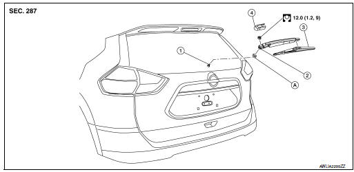
- Rear wiper motor
- Rear wiper arm
- Rear wiper blade
- Rear wiper arm cover
- Seal
Removal and Installation
REMOVAL
- Check that the rear wiper is in the auto stop position.
- Remove the rear wiper arm cover.
- Remove the rear wiper arm nut from the rear wiper arm.
- Remove the rear wiper arm.
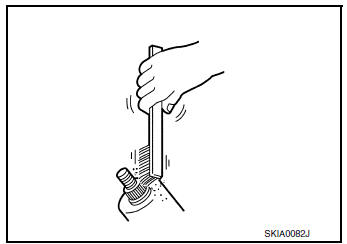
INSTALLATION
- Clean the rear wiper arm mount as shown, to prevent the possibility of rear wiper arm looseness.
- Check that the rear wiper is in the auto stop position.
- Adjust the rear wiper blade position. Refer to WW-70, "Adjustment".
- Install the rear wiper arm.
- Instal the rear wiper arm cover.
- Check that the rear wiper blades stop at the specified position. Refer to WW-70, "Adjustment".
Adjustment
- Defrosting wire
Position the wiper blade on top of the defrosting wire (A).
B: ± 7.5 mm (0.787 ± 0.295 in)
 Wiper and washer switch
Removal and Installation
The wiper and washer switch is serviced as a part of the combination switch.
Refer to BCS-76, "Removal and
Installation". ...
 Rear wiper motor
Exploded View
Rear wiper motor
Back door
Rear wiper motor harness
Removal and Installation
REMOVAL
Remove rear wiper arm. Refer to WW-69, "Removal and Installation&quo ...
Other materials:
Ignition coil
Exploded View
Ignition coil
Spark plug
Rocker cover
Removal and Installation
REMOVAL
Remove air duct assembly. Refer to EM-24, "Exploded View" .
Disconnect the harness connector from the ignition coil.
Remove the ignition coil.
CAUTION:
...
Divide-n-hide® adjustable floor (if so equipped)
Divide-n-hide® adjustable floor (if so equipped)
WARNINGDo not put objects heavier than 165 lbs
(75 kg) on the Divide-N-Hide® while in the
mid position. In the upper position, objects
should not weigh more than 30 lbs
(14 kg).
There are multiple positions for the adju ...
P2004 intake manifold runner control valve
DTC Description
DTC DETECTION LOGIC
DTC No.
CONSULT screen terms
(Trouble diagnosis content)
DTC detecting condition
P2004
TUMBLE CONT/V
(Intake manifold runner control stuck open
bank 1)
The target angle of intake manifold runner control valve controlled
b ...
