Nissan Rogue (T33) 2021-Present Service Manual: B24f5-93 Mode Door Motor
DTC Description
DTC DETECTION LOGIC
 NOTE:
NOTE:
If all of door motors DTC (B24F5-93, B24F6-93, B24F8-93) are detected, check ŌĆ£DOOR MOTORŌĆØ. Refer to Diagnosis Procedure.
| DTC No. |
CONSULT screen terms (Trouble diagnosis content) | DTC detection condition | |
|---|---|---|---|
| B24F5-93 |
Mode door motor (Mode door motor) |
Diagnosis condition | Ignition switch ON |
| Signal (Terminal) | LIN (door motor) signal | ||
| Threshold | Drive error of mode door motor is detected | ||
| Diagnosis delay time | 2 second or more | ||
POSSIBLE CAUSE
-
Harness and connector (mode door motor circuit is open or shorted to ground)
-
Mode door motor installation condition
-
Mode door motor
-
A/C amp.
FAIL-SAFE
ŌĆö
DTC CONFIRMATION PROCEDURE
PERFORM DTC CONFIRMATION PROCEDURE
 CONSULT
-
Start the engine.
-
Select "Self diagnosis result" mode of "HVAC".
-
Check DTC.
Is DTC detected?
YES>>Refer to Diagnosis Procedure.
NO-1>>To check malfunction symptom before repair: Refer to Intermittent Incident.
NO-2>>Confirmation after repair: Inspection End.
Diagnosis Procedure
CHECK MODE DOOR MOTOR POWER SUPPLY
-
Ignition switch ON.
-
Check voltage between mode door motor harness connector and A/C amp. harness connector.
| (+) | (ŌłÆ) | Voltage | ||
|---|---|---|---|---|
| Mode door motor | A/C amp. | |||
| Connector | Terminal | Connector | Terminal | |
| M143 | 1 | M55 | 58 | Battery voltage |
Is the inspection result normal?
YES>>GO TO 2.
NO>>GO TO 5.
CHECK MODE DOOR MOTOR GROUND CIRCUIT FOR OPEN
-
Ignition switch OFF.
-
Disconnect mode door motor connector and A/C amp. connector.
-
Check continuity between mode door motor harness connector and A/C amp. harness connector.
Mode door motor A/C amp. Continuity Connector Terminal Connector Terminal M143 2 M54 27 Yes
Is the inspection result normal?
YES>>GO TO 3.
NO>>Repair harness or connector.
CHECK MODE DOOR MOTOR LIN SIGNAL CIRCUIT
-
Connect mode door motor connector and A/C amp. connector.
-
Ignition switch ON.
-
Confirm output waveform between mode door motor harness connector and A/C amp. harness connector with oscilloscope.
(+) (ŌłÆ) Output waveform Mode door motor A/C amp. Connector Terminal Connector Terminal M143 3 M55 58 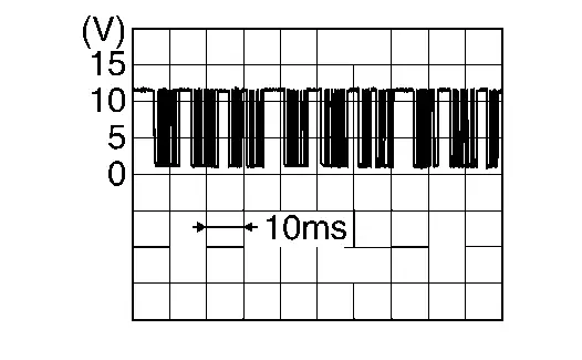
Is the inspection result normal?
YES>>GO TO 4.
NO>>GO TO 6.
CHECK INSTALLATION OF MODE DOOR MOTOR
Check mode door motor is properly installed. Refer to Exploded View.
Is the inspection result normal?
YES>>Replace mode door motor. Refer to Removal and Installation.
NO>>Repair or replace malfunctioning part.
CHECK MODE DOOR MOTOR POWER SUPPLY CIRCUIT FOR OPEN
-
Ignition switch OFF.
-
Disconnect mode door motor connector and A/C amp. connector.
-
Check continuity between mode door motor harness connector and A/C amp. harness connector.
Mode door motor A/C amp. Continuity Connector Terminal Connector Terminal M143 1 M54 1 Yes
Is the inspection result normal?
YES>>Replace A/C amp. Refer to Removal and Installation.
NO>>Repair harness or connector.
CHECK MODE DOOR MOTOR LIN SIGNAL CIRCUIT FOR OPEN
-
Ignition switch OFF.
-
Disconnect mode door motor connector and A/C amp. connector.
-
Check continuity between mode door motor harness connector and A/C amp. harness connector.
Mode door motor A/C amp. Continuity Connector Terminal Connector Terminal M143 3 M54 2 Yes
Is the inspection result normal?
YES>>Replace A/C amp. Refer to Removal and Installation.
NO>>Repair harness or connector.
Other materials:
Driver Assistance System. Preparation. Preparation
Preparation
Special Service Tools
The actual shape of the tools may differ from those illustrated here.
Tool number
(TechMate No.)
Tool name Description
ŌĆāŌĆāŌĆö
(NI-46534)
Trim Tool Set
Removing trim components
ŌĆö
(1ŌĆō20ŌĆō2851ŌĆō1)
ICC alignment kit*
...
System Description. System. Warning/indicator/chime List
Warning/indicator/chime List
Warning Lamp/Indicator Lamp/Information display
Warning lamp Item Design Reference
Seat belt warning lamp
For layout, refer to Design.
For function, refer to Seat Belt Warning Lamp.
Information display Item Reference
Rear seat belt warning
Ref ...
Dtc/circuit Diagnosis. Lin Communication Circuit
Moonroof Motor Assembly
Diagnosis Procedure
CHECK LIN COMMUNICATION SIGNAL
Ignition switch OFF.
Disconnect moonroof motor assembly harness connector.
Ignition switch ON.
Check signal between moonroof motor assembly harness connector and ground using an oscilloscope.
(+) (ŌĆö ...