
Nissan Rogue (T33) 2021-Present Service Manual: B24c6-12 Blower Motor Control
DTC Description
DTC DETECTION LOGIC
| DTC No. |
CONSULT screen terms (Trouble diagnosis content) | DTC detection condition | ||
|---|---|---|---|---|
| B24C6–12 |
BLOWER MOTOR CONTROL (Blower motor control) |
[CIRCUIT SHORT TO GROUND] | Diagnosis condition | When ignition switch is ON |
| Signal (Terminal) | Blower motor control signal | |||
| Threshold | Blower motor control signal circuit has a short to ground | |||
| Diagnosis delay time | — | |||
POSSIBLE CAUSE
-
Harness or connectors (blower motor control signal circuit is shorted to ground)
-
A/C amp.
FAIL-SAFE
—
DTC CONFIRMATION PROCEDURE
PERFORM SELF DIAGNOSIS RESULT
 CONSULT
-
Ignition switch ON.
-
Select "Self diagnosis result" mode of "HVAC".
-
Check DTC.
Is DTC detected?
YES>>Refer to DTC Diagnosis Procedure.
NO-1>>To check malfunction symptom before repair: Refer to Intermittent Incident.
NO-2>>Confirmation after repair: Inspection End.
DTC Diagnosis Procedure
CHECK FRONT BLOWER MOTOR CONTROL SIGNAL
-
Ignition switch ON.
-
Check duty ratios between front blower motor harness connector and ground by using an oscilloscope.
(+) (−) Condition Output waveform
(Approx.)Front blower motor Connector Terminal M144 1 Ground Front blower motor: OFF Battery voltage Front blower motor: 1st speed (manual) 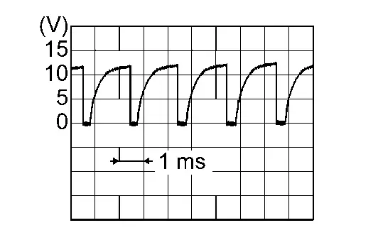
Front blower motor: 7th speed (manual) 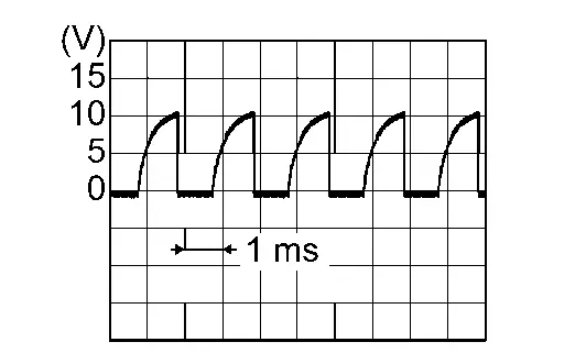
Is the inspection result normal?
YES>>Replace front blower motor. Refer to Removal and Installation.
NO>>GO TO 2.
CHECK FRONT BLOWER MOTOR CONTROL SIGNAL CIRCUIT FOR OPEN
-
Ignition switch OFF.
-
Disconnect front blower motor connector and A/C amp. connector.
-
Check continuity between front blower motor harness connector and A/C amp. harness connector.
Front blower motor A/C amp. Continuity Connector Terminal Connector Terminal M144 1 M50 34 Yes -
Check continuity between front blower motor harness connector and ground.
Front blower motor (—) Continuity Connector Terminal M144 1 Ground Yes
Is the inspection result normal?
YES>>Replace the A/C amp. Refer to Removal and Installation.
NO>>Repair the harnesses or connectors.
Other materials:
Can Gateway. Basic Inspection. Additional Service When Replacing 8ch Can Gateway
Additional Service When Replacing 8ch Can Gateway
Work Procedure
DescriptionWhen replacing the 8CH gateway, perform "Procedure before replacing" and "Procedure after replacing"CAUTION:
Never reuse the parts which has been dropped
Dispose 8CH CAN gateway which is paired with Intelligent K ...
Basic Inspection. Diagnosis and Repair Work Flow
Work Flow
OVERALL SEQUENCEDETAILED FLOWGET INFORMATION FOR SYMPTOM
Get detailed information from the customer about the symptom (the
condition and the environment when the incident/malfunction occurs).
Check operation condition of the function that is malfunctioning.
>>
G ...
Protection contre la corrosion
Facteurs de corrosion les plus courants
Accumulation de poussière humide, de sable et de débris dans les panneaux de carrosserie, les orifices et les zones peu ventilées.
Dommages de la peinture ou des revêtements protecteurs causés par des projections de gravillons ou de petits accidents ...