Nissan Rogue (T33) 2021-Present Service Manual: B24f5-93 Mode Door Motor
DTC Description
DTC DETECTION LOGIC
 NOTE:
NOTE:
If all of door motors DTC (B2480-93*, B24F5-93, B24F6-93, B24F7-93, B24F8-93) are detected, check ŌĆ£DOOR MOTORŌĆØ. Refer to Diagnosis Procedure.
*: With rear air control
| DTC No. |
CONSULT screen terms (Trouble diagnosis content) | DTC detection condition | |
|---|---|---|---|
| B24F5-93 |
Mode door motor (Mode door motor) |
Diagnosis condition | Ignition switch ON |
| Signal (Terminal) | LIN (door motor) signal | ||
| Threshold | Drive error of mode door motor is detected | ||
| Diagnosis delay time | 2 second or more | ||
POSSIBLE CAUSE
-
Harness and connector (mode door motor circuit is open or shorted to ground)
-
Mode door motor installation condition
-
Mode door motor
-
A/C amp.
FAIL-SAFE
ŌĆö
DTC CONFIRMATION PROCEDURE
PERFORM DTC CONFIRMATION PROCEDURE
 CONSULT
-
Start the engine.
-
Select ŌĆ£Self diagnosis resultŌĆØ mode of ŌĆ£HVACŌĆØ.
-
Check DTC.
Is DTC detected?
YES>>Refer to Diagnosis Procedure.
NO-1>>To check malfunction symptom before repair: Refer to Intermittent Incident.
NO-2>>Confirmation after repair: Inspection End.
DTC Diagnosis Procedure
CHECK MODE DOOR MOTOR POWER SUPPLY
-
Ignition switch ON.
-
Check voltage between mode door motor harness connector and A/C amp. harness connector.
| (+) | (ŌłÆ) | Voltage | ||
|---|---|---|---|---|
| Mode door motor | A/C amp. | |||
| Connector | Terminal | Connector | Terminal | |
| M143 | 1 | M55 | 58 | Battery voltage |
Is the inspection result normal?
YES>>GO TO 2.
NO>>GO TO 5.
CHECK MODE DOOR MOTOR GROUND CIRCUIT FOR OPEN
-
Ignition switch OFF.
-
Disconnect mode door motor connector and A/C amp. connector.
-
Check continuity between mode door motor harness connector and A/C amp. harness connector.
Mode door motor A/C amp. Continuity Connector Terminal Connector Terminal M143 2 M54 27 Yes
Is the inspection result normal?
YES>>GO TO 3.
NO>>Repair harness or connector.
CHECK MODE DOOR MOTOR LIN SIGNAL CIRCUIT
-
Connect mode door motor connector and A/C amp. connector.
-
Ignition switch ON.
-
Confirm output waveform between mode door motor harness connector and A/C amp. harness connector with oscilloscope.
(+) (ŌłÆ) Output waveform Mode door motor A/C amp. Connector Terminal Connector Terminal M143 3 M55 58 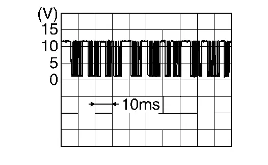
Is the inspection result normal?
YES>>GO TO 4.
NO>>GO TO 6.
CHECK INSTALLATION OF MODE DOOR MOTOR
Check mode door motor is properly installed. Refer to Exploded View.
Is the inspection result normal?
YES>>Replace mode door motor. Refer to Removal and Installation.
NO>>Repair or replace malfunctioning part.
CHECK MODE DOOR MOTOR POWER SUPPLY CIRCUIT FOR OPEN
-
Ignition switch OFF.
-
Disconnect mode door motor connector and A/C amp. connector.
-
Check continuity between mode door motor harness connector and A/C amp. harness connector.
Mode door motor A/C amp. Continuity Connector Terminal Connector Terminal M143 1 M54 1 Yes
Is the inspection result normal?
YES>>Replace A/C amp. Refer to Removal and Installation.
NO>>Repair harness or connector.
CHECK MODE DOOR MOTOR LIN SIGNAL CIRCUIT FOR OPEN
-
Ignition switch OFF.
-
Disconnect mode door motor connector and A/C amp. connector.
-
Check continuity between mode door motor harness connector and A/C amp. harness connector.
Mode door motor A/C amp. Continuity Connector Terminal Connector Terminal M143 3 M54 2 Yes
Is the inspection result normal?
YES>>Replace A/C amp. Refer to Removal and Installation.
NO>>Repair harness or connector.
Other materials:
Removal and Installation. Tire Pressure Sensor
Exploded View
Screw
Tire pressure sensor
Valve
Valve core
Valve cap
: Comply with the assembly procedure when tightening. Refer to Removal and Installation.
: N┬Ęm (kg-m, in-lb)
: Always replace after every disassembly.
Removal & Install ...
Intelligent Key operation (models with
request switch)
Example
Example
You can conveniently lock or unlock the doors of your Nissan Rogue without taking the key out of your pocket or bag.
When you carry the Intelligent Key with you, the Nissan Rogue allows controlling all doors by pressing the door handle request switch
A (front doors) or the liftg ...
Power Supply and Ground Circuit
Ecm
Diagnosis Procedure
CHECK THE BATTERY CABLE
Turn ignition switch OFF.
Check the battery cable for tightening enough.
NOTE:
Check the continuity between the battery cable and the battery terminal.
Is the inspection result normal?
YES>>
GO TO 2
...