Nissan Rogue (T33) 2021-Present Service Manual: B2480-93 Rear Air Mix Door Motor
DTC Description
DTC DETECTION LOGIC
 NOTE:
NOTE:
If all of door motors DTC (B2480-93*, B24F5-93, B24F6-93, B24F7-93, B24F8-93) are detected, check ŌĆ£DOOR MOTORŌĆØ. Refer to Diagnosis Procedure.
*: With rear air control
| DTC No. |
CONSULT screen terms (Trouble diagnosis content) | DTC detection condition | |
|---|---|---|---|
| B2480-93 |
Rear air mix door motor (Rear air mix door motor) |
Diagnosis condition | Ignition switch ON |
| Signal (Terminal) | LIN (door motor) signal | ||
| Threshold | Drive error of air mix door motor (rear) is detected | ||
| Diagnosis delay time | 1 second or more | ||
POSSIBLE CAUSE
-
Harness and connector [air mix door motor (rear) circuit is open or shorted to ground]
-
Air mix door motor (rear) installation condition
-
Air mix door motor (rear)
-
A/C amp.
FAIL-SAFE
ŌĆö
DTC CONFIRMATION PROCEDURE
PERFORM SELF-DIAGNOSIS
 CONSULT
-
Start the engine.
-
Select ŌĆ£Self diagnosis resultŌĆØ mode of ŌĆ£HVACŌĆØ.
-
Check DTC.
Is DTC detected?
YES>>Refer to Diagnosis Procedure.
NO-1>>To check malfunction symptom before repair: Refer to Intermittent Incident.
NO-2>>Confirmation after repair: Inspection End.
DTC Diagnosis Procedure
CHECK AIR MIX DOOR MOTOR (REAR) POWER SUPPLY
-
Ignition switch ON.
-
Check voltage between air mix door motor (rear) harness connector and A/C amp. harness connector.
| (+) | (ŌłÆ) | Voltage | ||
|---|---|---|---|---|
| Air mix door motor (rear) | A/C amp. | |||
| Connector | Terminal | Connector | Terminal | |
| M151 | 1 | M55 | 58 | Battery voltage |
Is the inspection result normal?
YES>>GO TO 2.
NO>>GO TO 5.
CHECK AIR MIX DOOR MOTOR (REAR) GROUND CIRCUIT FOR OPEN
-
Ignition switch OFF.
-
Disconnect air mix door motor (rear) connector and A/C amp. connector.
-
Check continuity between air mix door motor (rear) harness connector and A/C amp. harness connector.
Air mix door motor (rear) A/C amp. Continuity Connector Terminal Connector Terminal M151 2 M54 27 Yes
Is the inspection result normal?
YES>>GO TO 3.
NO>>Repair harness or connector.
CHECK AIR MIX DOOR MOTOR (REAR) LIN SIGNAL CIRCUIT
-
Connect air mix door motor (rear) connector and A/C amp. connector.
-
Ignition switch ON.
-
Confirm output waveform between air mix door motor (rear) harness connector and A/C amp. harness connector with oscilloscope.
(+) (ŌłÆ) Output waveform Air mix door motor (rear) A/C amp. Connector Terminal Connector Terminal M151 3 M55 58 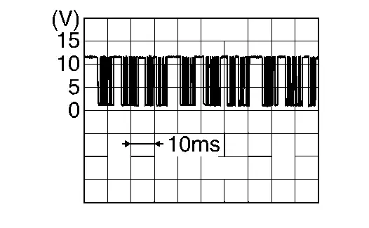
Is the inspection result normal?
YES>>GO TO 4.
NO>>GO TO 6.
CHECK INSTALLATION OF AIR MIX DOOR MOTOR (REAR)
Check air mix door motor (rear) is properly installed. Refer to Exploded View.
Is the inspection result normal?
YES>>Replace air mix door motor (rear). Refer to Removal and Installation.
NO>>Repair or replace malfunctioning part.
CHECK AIR MIX DOOR MOTOR (REAR) POWER SUPPLY CIRCUIT FOR OPEN
-
Ignition switch OFF.
-
Disconnect air mix door motor (rear) connector and A/C amp. connector.
-
Check continuity between air mix door motor (rear) harness connector and A/C amp. harness connector.
Air mix door motor (rear) A/C amp. Continuity Connector Terminal Connector Terminal M151 1 M54 1 Yes
Is the inspection result normal?
YES>>Replace A/C amp. Refer to Removal and Installation.
NO>>Repair harness or connector.
CHECK AIR MIX DOOR MOTOR (REAR) LIN SIGNAL CIRCUIT FOR OPEN
-
Ignition switch OFF.
-
Disconnect air mix door motor (rear) connector and A/C amp. connector.
-
Check continuity between air mix door motor (rear) harness connector and A/C amp. harness connector.
Air mix door motor (rear) A/C amp. Continuity Connector Terminal Connector Terminal M151 3 M54 2 Yes
Is the inspection result normal?
YES>>Replace A/C amp. Refer to Removal and Installation.
NO>>Repair harness or connector.
Other materials:
U0079-00 Can Comm Circuit
DTC Description
DESCRIPTIONCAN (Controller Area Network) is a serial
communication line for real-time application. It is an onNissan Ariya
vehicle multiplex communication line with high data communication speed
and excellent error detection ability. Many electronic control units are
equippe ...
If your vehicle overheats
WARNING
Never continue driving if your vehicle overheats ŌĆö this can lead to engine failure or even a vehicle fire.
Never open the hood if steam is coming out.
Never remove the radiator or coolant reservoir cap when the engine is hot. Pressurized coolant can spray out and cause serious ...
Side Radar Front Lh
Reference Value
VALUES ON THE DIAGNOSIS TOOL Monitor item Condition Value/Status
Horizontal alignment value
When the ignition switch ON and the side radar adjustment is completed
Displays the horizontal alignment value
TERMINAL LAYOUTPHYSICAL VALUES
Terminal No.
(Wire color) Descr ...