
Nissan Rogue (T33) 2021-Present Service Manual: Automatic Air Conditioning :: Ecu Diagnosis Information
A/c Amp.
Values on the Diagnosis Tool
 NOTE:
NOTE:
The following table includes information (items) inapplicable to this Nissan Ariya vehicle. For information (items) applicable to this vehicle, refer to CONSULT display items.
| Monitor item | Condition | Value/Status | |
|---|---|---|---|
| FAN REQ SIG | Engine: Run at idle after warming up | Front blower motor: ON | On |
| Front blower motor: OFF | Off | ||
| A/C compressor clutch status | Engine: Run at idle after warming up | A/C switch: ON | On |
| A/C switch: OFF | Off | ||
| Compressor request signal | Engine: Run at idle after warming up | A/C switch: ON | On |
| A/C switch: OFF | Off | ||
| Blower fan request signal | Ignition switch ON | On | |
| Off | |||
| ODO/TRIP METER | Ignition switch ON | Equivalent to odometer reading | |
| Rear XM | Ignition switch ON |
Value according to target air flow temperature (rear) [Display range: -100 - 150°C (-148 - 302°F)] |
|
| XM | Ignition switch ON |
Value according to target air flow temperature (driver side) [Display range: -100 - 150°C (-148 - 302°F)] |
|
| PASS IN CAL | Ignition switch ON |
Equivalent to passenger side in-Nissan Ariya vehicle temperature [Display range: -40 - 100°C (-40 - 212°F)] |
|
| Compressor ECV duty | Engine Running | (Display range: 0 - 100%) | |
| Nissan Ariya Vehicle speed | When driving the vehicle | Equivalent to speedometer reading | |
| AMB TEMP SEN | Ignition switch ON |
Equivalent to ambient temperature [Display range: -50 - 70°C (-58 - 158°F)] |
|
| Intake temperature sensor value | Ignition switch ON |
Equivalent to evaporator fin temperature [Display range: -40 - 100°C (-40 - 212°F)] |
|
| In-Nissan Ariya vehicle temperature sensor | Ignition switch ON |
Equivalent to in-Nissan Ariya vehicle temperature [Display range: -40 - 100°C (-40 - 212°F)] |
|
| Blower fan duty | Engine: Run at idle after warming up | Front blower motor: ON |
|
| Front blower motor: OFF | 0 | ||
| Assist seat target air temperature | Ignition switch ON |
Value according to target air flow temperature (passenger side) [Display range: -100 - 150°C (-148 - 302°F)] |
|
| Engine RPM | Engine: Running | Equivalent to tachometer reading | |
| Engine coolant temperature | Ignition switch ON | Equivalent to engine coolant temperature | |
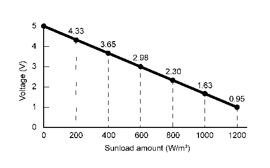
| Sunload sensor calculation value | Ignition switch ON |
Equivalent to sunload amount (Display range: 0 - 1045 W/m^2) |
|
| Intake temperature sensor calculation value | Ignition switch ON |
Equivalent to evaporator fin temperature [Display range: -40 - 100°C (-40 - 212°F)] |
|
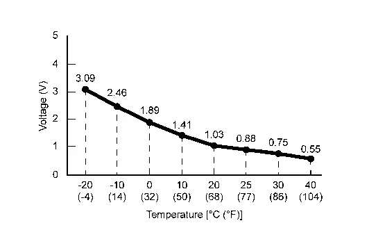
| In-Nissan Ariya vehicle temperature sensor value | Ignition switch ON |
Equivalent to in-Nissan Ariya vehicle temperature [Display range: -40 - 100°C (-40 - 212°F)] |
|
| Ambient temperature sensor calculation value | Ignition switch ON |
Equivalent to ambient temperature [Display range: -40 - 100°C (-40 - 212°F)] |
|
| Sun load sensor value | Ignition switch ON |
Equivalent to sunload amount (Display range: 0 - 1045 W/m^2) |
|
Reference Value
TERMINAL LAYOUT
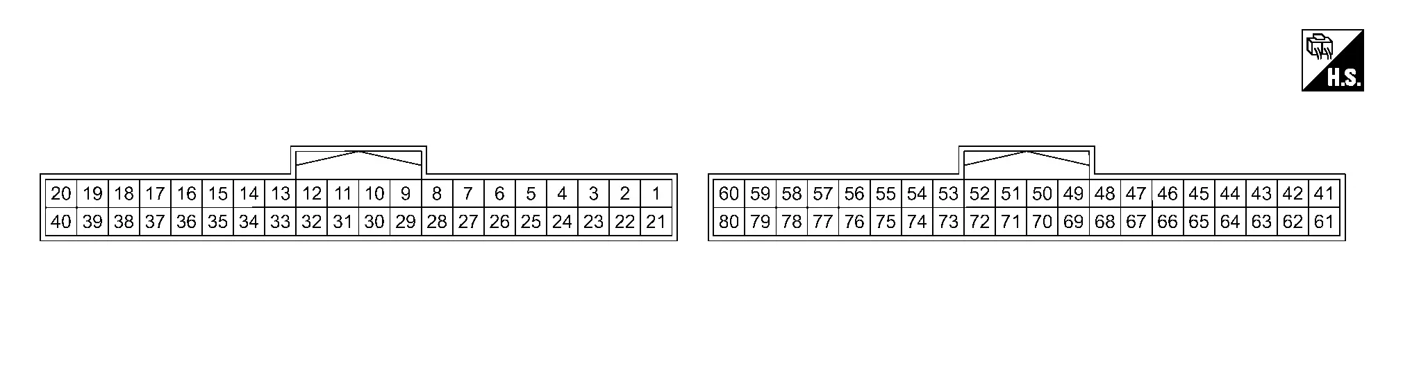
PHYSICAL VALUES
|
Terminal No. (Wire color) | Description | Condition |
Value (Approx.) | ||||
|---|---|---|---|---|---|---|---|
| (+) | (−) | Signal name | Input/Output | ||||
|
1 (LA/LG) |
58 (B) |
Door motor power supply | Output | Ignition switch ON | Battery voltage | ||
|
2 (LA/G) |
58 (B) |
LIN communication (door motor) | Input/Output | Ignition switch ON |
|
||
|
23 (LA/SB) |
26 (BR) |
Intake sensor signal | Input | Ignition switch ON |
|
||
|
26 (BR) |
Ground | Sensor ground (intake) | — | Ignition switch ON | 0 V | ||
|
27 (LA/B) |
Ground | Door motor ground | — | Ignition switch ON | 0 V | ||
|
34 (G) |
58 (B) |
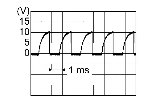
Blower motor control | Output | Ignition switch ON | Front blower motor: OFF | Battery voltage | |
| Front blower motor: 1st speed (manual) |
|
||||||
| Front blower motor: 7th speed (manual) |
|
||||||
|
45 (LA/G) |
58 (B) |
LIN communication (heated seat) | Input/Output | Ignition switch ON |
|
||
|
47 (G) |
78 (W) |
Sunload sensor signal | Input | Ignition switch ON |
|
||
|
48 (Y) |
78 (W) |
In-Nissan Ariya vehicle sensor signal | Input | Ignition switch ON |
|
||
|
50 (LA/L) |
— | CAN-High | Input/Output | — | — | ||
|
56 (BG) |
58 (B) |
Heated steering wheel relay control signal | Output | Engine running | Heated steering wheel switch: ON | 0 V | |
| Other than the above | Battery voltage | ||||||
|
58 (B) |
Ground | Ground | — | Ignition switch ON | 0 V | ||
|
60 (LA/R) |
58 (B) |
Accessory power supply | Input | Ignition switch OFF (auto ACC status) or ON | Battery voltage | ||
| Ignition switch OFF (not auto ACC status) | 0 V | ||||||
|
68 (LA/P)1 (LA/Y)2 |
58 (B) |
LIN communication (A/C control) | Input/Output | Ignition switch ON |
|
||
|
70 (LA/P) |
— | CAN-Low | Input/Output | — | — | ||
|
78 (W) |
Ground | Sensor ground (in-Nissan Ariya vehicle, sunload) | — | Ignition switch ON | 0 V | ||
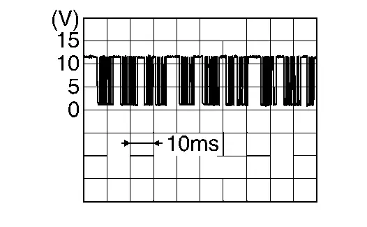
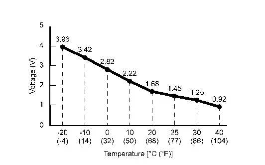
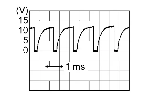
1: Japan production
2: USA production
Fail-safe
FAIL-SAFE FUNCTION
-
A/C amp. performs fail-safe control when any DTC are detected.
DTC CONSULT screen terms (Trouble diagnosis content) Fail-safe B24A6-11 IN-Nissan Ariya Vehicle SENSOR In-vehicle temperature is calculated as 25°C (77°F) and air conditioning system is controlled. B24A6-15 IN-Nissan Ariya Vehicle SENSOR -
If a CAN communication error exists between the A/C amp., ECM, IPDM E/R, BCM and combination meter for 2 seconds or longer, air conditioning is controlled under the following conditions:
A/C compressor : OFF -
If a LIN communication error exists between the A/C amp. and A/C switch assembly for 30 seconds or longer, air conditioning is controlled under the following conditions:
A/C compressor : ON Air outlet : AUTO Air inlet : AUTO Front blower fan speed : AUTO Set temperature : Setting before communication error occurs
DTC Index
×: Applicable
| DTC |
Items (CONSULT screen terms) | Fail-safe | Reference |
|---|---|---|---|
| B2480-93 | REAR AIR MIX DOOR MOTOR | — | DTC Description |
| B2490-13 | FRONT SEAT HEATER LH | — | DTC Description |
| B2490-19 | FRONT SEAT HEATER LH | — | DTC Description |
| B2492-13 | FRONT SEAT HEATER RH | — | DTC Description |
| B2492-19 | FRONT SEAT HEATER RH | — | DTC Description |
| B2494-13 | HEATED STEERING WHEEL RELAY | — | DTC Description |
| B2494-19 | HEATED STEERING WHEEL RELAY | — | DTC description |
| B2495-13 | REAR SEAT HEATER LH | — | DTC Description |
| B2495-19 | REAR SEAT HEATER LH | — | DTC Description |
| B2496-13 | REAR SEAT HEATER RH | — | DTC Description |
| B2496-19 | REAR SEAT HEATER RH | — | DTC Description |
| B24A0-49 | A/C AUTO AMP. | — | DTC Description |
| B24A1-16 | A/C AUTO AMP. POWER SUPPLY | — | DTC Description |
| B24A1-17 | A/C AUTO AMP. | — | DTC Description |
| B24A2-55 | CONFIGURATION NOT IMPLEMENT | — | DTC Description |
| B24A4-11 | INTAKE SENSOR | — | DTC Description |
| B24A4-15 | INTAKE SENSOR | — | DTC Description |
| B24A6-11 | IN-Nissan Ariya Vehicle SENSOR | × | DTC Description |
| B24A6-15 | IN-Nissan Ariya Vehicle SENSOR | × | DTC Description |
| B24B4-02 | A/C CONTROL COMM | — | DTC Description |
| B24C6-12 | BLOWER MOTOR CONTROL | — | DTC Description |
| B24C6-14 | BLOWER MOTOR CONTROL | — | DTC Description |
| B24F4-12 | HEATED STEERING WHEEL RELAY | — | DTC Description |
| B24F4-14 | HEATED STEERING WHEEL RELAY | — | DTC Description |
| B24F5-93 | MODE DOOR MOTOR | — | DTC Description |
| B24F6-93 | INTAKE DOOR MOTOR | — | DTC Description |
| B24F7-93 | AIR MIX DOOR MOTOR 1 | — | DTC Description |
| B24F8-93 | AIR MIX DOOR MOTOR 2 | — | DTC Description |
| U1CA1-08 | LIN COMMUNICATION 2 | — | DTC Description |
| U1CA2-08 | LIN COMMUNICATION 3 | — | DTC Description |
| U1CA3-08 | LIN COMMUNICATION 4 | — | DTC Description |
| U1CA6-02 | FRONT SEAT HEATER RH COMMUNICATION | — | DTC Description |
| U1CA7-02 | FRONT SEAT HEATER LH COMMUNICATION | — | DTC Description |
| U1CA8-02 | REAR SEAT HEATER RH COMMUNICATION | — | DTC Description |
| U1CA9-02 | REAR SEAT HEATER LH COMMUNICATION | — | DTC Description |
| U1CAA-02 | MODE DOOR MOTOR | — | DTC Description |
| U1CAB-02 | INTAKE DOOR MOTOR | — | DTC Description |
| U1CAC-02 | AIR MIX DOOR MOTOR 1 | — | DTC Description |
| U1CAD-02 | AIR MIX DOOR MOTOR 2 | — | DTC Description |
| U1CAE-02 | REAR AIR MIX DOOR MOTOR | — | DTC Description |
| U1CB1-02 | A/C CONTROL 2 COMMUNICATION | — | DTC Description |
×: Applicable
| DTC |
Items (CONSULT screen terms) | Fail-safe | Reference |
|---|---|---|---|
| U2140-87 | CAN COMM ERR (ECM) | — | DTC Description |
| U2148-87 | CAN COMM ERR (BRAKE CONTROL UNIT) | — | DTC Description |
| U214E-87 | CAN COMM ERR (COMBINATION METER) | — | DTC Description |
| U214F-87 | CAN COMM ERR (BCM) | — | DTC Description |
| U2154-87 | CAN COMM ERR (MIU) | — | DTC Description |
| U215B-87 | CAN COMM ERR (IPDM E/R) | — | DTC Description |
Bcm, Ecm, Ipdm E/r
List of ECU Reference
| ECU | Reference | |
|---|---|---|
| BCM | Values on the Diagnosis Tool | |
| Reference Value (With Type A Meter) | ||
| Reference Value (With Type B Meter) | ||
| Fail-safe | ||
| DTC Inspection Priority Chart | ||
| DTC Index | ||
| ECM | Values On The Diagnosis Tool | |
| Physical Values | ||
| Fail-safe | ||
| DTC Inspection Priority Chart | ||
| DTC Index | ||
| Test Value and Test Limit | ||
| IPDM E/R | Values on the Diagnosis Tool | |
| Reference Value | ||
| Fail-safe | ||
| DTC Inspection Priority Chart | ||
| DTC Index | ||
Other materials:
P0365 Exhaust Camshaft Position Sensor
DTC Description
DTC DETECTION LOGIC
Exhaust camshaft position sensor signal is not sent to ECM during engine running.
The pulse signal sent from the exhaust camshaft position sensor to ECM is not in the normal pattern during engine running.
DTC
CONSULT screen terms
(Trouble diagnos ...
Dtc/circuit Diagnosis. Memory Indicator
Component Function Check
CHECK FUNCTION
Push set switch.
Check memory indicator operation.
When driver seat position is already retained in memory
: Illuminated for 5 seconds
When driver seat position is not retained in memory
: Illuminated for 0.5 second
Is the ins ...
System Description. Component Parts. Wiper and Washer System
Wiper and Washer System
Component Parts Location
Component Parts Location A.
View with washer tank removed from Nissan Ariya vehicle (for USA)
B.
View with washer tank removed from vehicle
C.
Behind LH side of front fascia assembly (view with front fascia assembly) removed
No. ...