Nissan Rogue (T33) 2021-Present Service Manual: Automatic Air Conditioning :: Basic Inspection
Diagnosis and Repair Work Flow
Work Flow
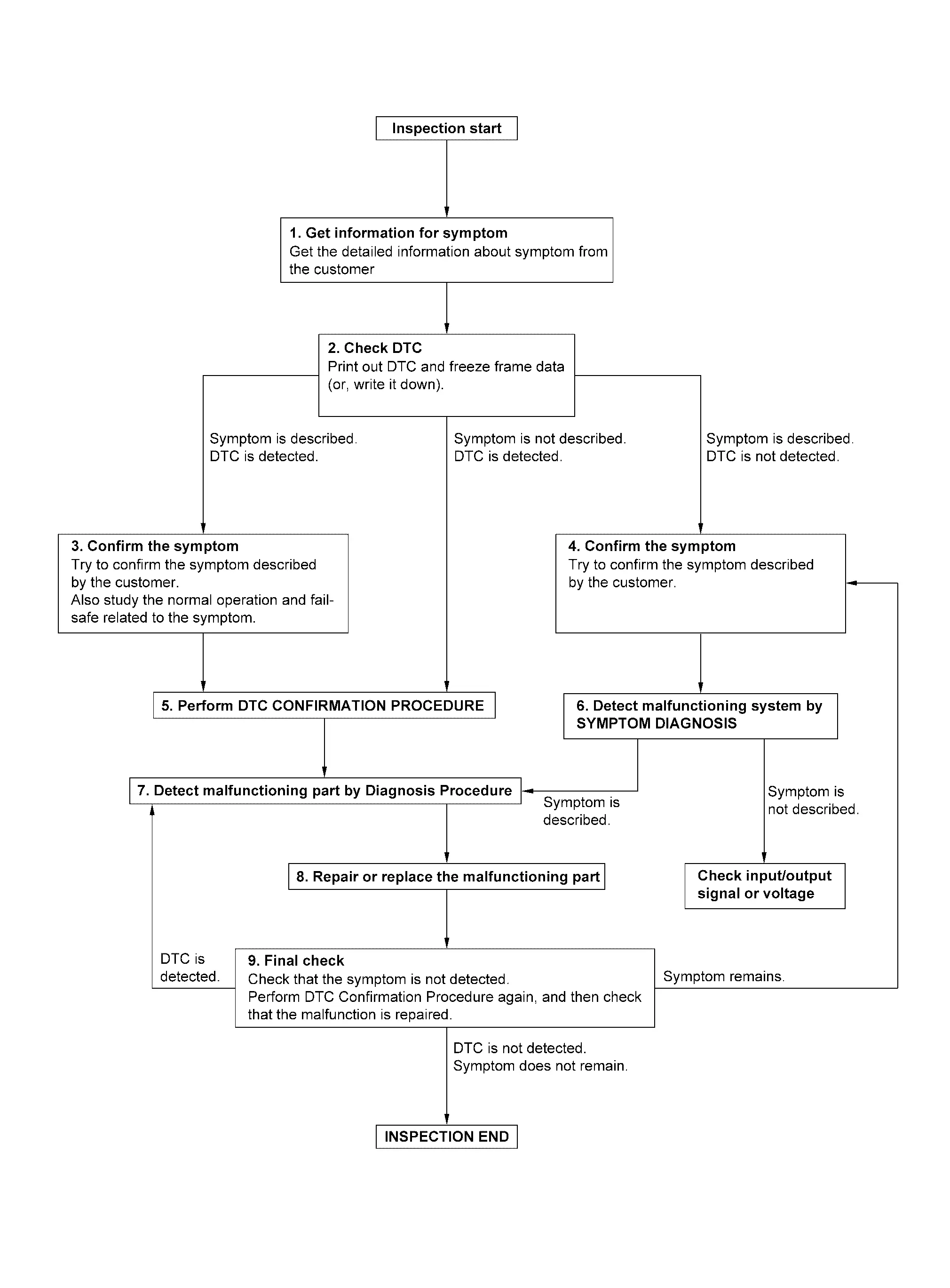
OVERALL SEQUENCE
DETAILED FLOW
GET INFORMATION FOR SYMPTOM
-
Get detailed information from the customer about the symptom (the condition and the environment when the incident/malfunction occurs).
-
Check operation condition of the function that is malfunctioning.
>>
GO TO 2.
CHECK DTC
 CONSULT
-
Check DTC.
-
Perform the following procedure if DTC is detected:
-
Record DTC and freeze frame data (print them out).
-
Erase DTC.
-
Study the relationship between the cause detected by DTC and the symptom described by the customer.
-
Are any symptoms described and any DTC detected?
Symptom is described, DTC is detected>>GO TO 3.
Symptom is described, DTC is not detected>>GO TO 4.
Symptom is not described, DTC is detected>>GO TO 5.
CONFIRM THE SYMPTOM
Try to confirm the symptom described by the customer.
Also study the normal operation and fail-safe related to the symptom.
Verify relation between the symptom and the condition when the symptom is detected.
>>
GO TO 5.
CONFIRM THE SYMPTOM
Try to confirm the symptom described by the customer.
Verify relation between the symptom and the condition when the symptom is detected.
>>
GO TO 6.
PERFORM DTC CONFIRMATION PROCEDURE
CONSULT
Perform DTC CONFIRMATION PROCEDURE for the detected DTC, and then check that DTC is detected again. At this time, always connect CONSULT to the Nissan Ariya vehicle, and check "Self diagnosis result" in real time.
If two or more DTCs are detected, refer to DTC INSPECTION PRIORITY CHART, and determine trouble diagnosis order.
 NOTE:
NOTE:
-
Freeze frame data is useful if the DTC is not detected.
-
Perform Component Function Check if DTC CONFIRMATION PROCEDURE is not included on Service Manual. This simplified check procedure is an effective alternative though DTC cannot be detected during this check.
If the result of Component Function Check is NG, it is the same as the detection of DTC by DTC CONFIRMATION PROCEDURE.
Is DTC detected?
YES>>GO TO 7.
NO>>Refer to Intermittent Incident.
DETECT MALFUNCTIONING SYSTEM BY SYMPTOM DIAGNOSIS
CONSULT
Detect malfunctioning system according to SYMPTOM DIAGNOSIS based on the confirmed symptom in step 4, and determine the trouble diagnosis order based on possible causes and symptom.
Is the symptom described?
YES>>GO TO 7.
NO>>Monitor input data from related sensors or check voltage of related module terminals.
DETECT MALFUNCTIONING PART BY DIAGNOSIS PROCEDURE
Inspect according to Diagnosis Procedure of the system.
Is malfunctioning part detected?
YES>>GO TO 8.
NO>>Refer to Intermittent Incident.
REPAIR OR REPLACE THE MALFUNCTIONING PART
CONSULT
-
Repair or replace the malfunctioning part.
-
Reconnect parts or connectors disconnected during Diagnosis Procedure again after repair and replacement.
-
Check DTC. If DTC is detected, erase it.
>>
GO TO 9.
FINAL CHECK
CONSULT
When DTC is detected in step 2, perform DTC CONFIRMATION PROCEDURE again, and then check that the malfunction is repaired securely.
When symptom is described by the customer, refer to confirmed symptom in step 3 or 4, and check that the symptom is not detected.
Is DTC detected and does symptom remain?
YES-1>>DTC is detected: GO TO 7.
YES-2>>Symptom remains: GO TO 4.
NO>>Before returning the Nissan Ariya vehicle to the customer, always erase DTC.
Operation Inspection
Work Procedure
DESCRIPTION
The purpose of the operation inspection is to check that the individual system operates normally.
| Check condition | : Engine running at normal operating temperature. |
OPERATION INSPECTION
CHECK MEMORY FUNCTION
-
Press AUTO switch to activate air conditioning.
-
Set temperature to 32.0┬░C (89┬░F) by operating temperature control dial (driver side).
-
Press ON┬ĘOFF switch.
-
Ignition switch OFF.
-
Ignition switch ON.
-
Press AUTO switch.
-
Check that the set temperature 32.0┬░C (89┬░F) is maintained.
Is the inspection result normal?
YES>>GO TO 2.
NO>>GO TO 11.
CHECK FAN SPEED
-
Start engine.
-
Operate fan switch and check that fan speed changes.
-
Check operation for all fan speeds.
Is the inspection result normal?
YES>>GO TO 3.
NO>>GO TO 11.
CHECK AIR OUTLET
-
Operate fan switch to set the fan speed to maximum speed.
-
Operate MODE switch and DEF switch.
-
Check that air outlets change according to each indicated air outlet by placing a hand in front of the outlets.
Is the inspection result normal?
YES-1>>With rear air control: GO TO 4.
YES-2>>Without rear air control: GO TO 5.
NO>>GO TO 11.
CHECK AIR INLET (WITH REAR AIR CONTROL)
-
Press REC switch to set the air inlet to recirculation. The REC switch indicator turns ON.
-
Listen to intake sound and confirm air inlets change.
-
Press FRE switch again to set the air inlet to fresh air intake. The FRE switch indicator turns ON.
-
Listen to intake sound and confirm air inlets change.
Is the inspection result normal?
YES>>GO TO 6.
NO>>GO TO 11.
CHECK AIR INLET (WITHOUT REAR AIR CONTROL)
-
Press intake switch to set the air inlet to recirculation. The intake switch indicator turns ON.
-
Listen to intake sound and confirm air inlets change.
-
Press intake switch again to set the air inlet to fresh air intake. The intake switch indicator turns OFF.
-
Listen to intake sound and confirm air inlets change.
Is the inspection result normal?
YES>>GO TO 6.
NO>>GO TO 11.
CHECK A/C COMPRESSOR
-
Press A/C switch. The A/C switch indicator turns ON.
-
Check visually and by sound that the A/C compressor operates.
-
Press A/C switch again. The A/C switch indicator turns OFF.
-
Check that A/C compressor stops.
Is the inspection result normal?
YES>>GO TO 7.
NO>>GO TO 11.
CHECK DISCHARGE AIR TEMPERATURE
-
Operate temperature control dial (driver side).
-
Check that discharge air temperature (driver side) changes.
-
Operate temperature control dial (passenger side).
-
Check that discharge air temperature (passenger side) changes.
-
Operate temperature control switch (rear air control).
-
Check that discharge rear air temperature changes.
-
Press SYNC switch. SYNC switch indicator turns ON.
-
Check that air temperature setting [front (driver side/passenger side) / rear] is unified to the driver side temperature setting.
Is the inspection result normal?
YES>>GO TO 8.
NO>>GO TO 11.
CHECK WITH TEMPERATURE SETTING LOWERED
-
Operate A/C compressor.
-
Operate temperature control dial (driver side) to lower the set temperature to "Lo".
-
Check that cool air blows from the air outlets.
Is the inspection result normal?
YES>>GO TO 9.
NO>>GO TO 11.
CHECK TEMPERATURE INCREASE
-
Warm up engine to the normal operating temperature.
-
Operate temperature control dial (driver side) to raise the set temperature to "Hi".
-
Check that warm air blows from the air outlets.
Is the inspection result normal?
YES>>GO TO 10.
NO>>GO TO 11.
CHECK AUTO MODE
-
Press AUTO switch and check that AUTO indicator turns ON.
-
Operate temperature control switch (driver side) to check that fan speed or air outlet changes (the air outlet or fan speed varies depending on the ambient temperature, in-Nissan Ariya vehicle temperature, set temperature, and etc.).
Is the inspection result normal?
YES>>Inspection End.
NO>>GO TO 11.
CHECK SELF DIAGNOSIS
CONSULT
-
Select "Self diagnosis result" mode of "HVAC".
-
Check that any DTC is detected.
Is any DTC detected?
YES>>Refer to DTC Index, and perform the appropriate diagnosis.
NO>>GO TO 12.
CHECK FAIL-SAFE ACTIVATION
Check that symptom is applied to the fail-safe activation. Refer to Fail-safe.
>>
Refer to Symptom Table, and perform the appropriate diagnosis.
Additional Service When Replacing A/c Amp.
Description
After replaced A/C amp. it is necessary to perform control unit configuration with CONSULT. For details, refer to Work Procedure.
AFTER REPLACEMENT
CAUTION:
-
When replacing A/C amp. write vehicle specification with CONSULT vehicle configuration.
-
Never perform Nissan Ariya vehicle configuration other than performing with new A/C amp. or the control function may not operate normally.
Work Procedure
REPLACE A/C AMP.
Replace A/C amp. Refer to Removal and Installation.
>>
GO TO 2.
WRITING Nissan Ariya Vehicle SPECIFICATION
Perform configuration (HVAC). Refer to Description.
>>
Work End.
Configuration (hvac)
Description
Vehicle specification needs to be written with CONSULT because it is not written after replacing the A/C amp.
The configuration requires network connection. CONSULT connects to network and then it downloads the configuration data from the server. Then CONSULT writes the Nissan Ariya vehicle specification to the A/C amp.
Refer to Work Procedure.
NOTE:
For details the network connection and operation, refer to ŌĆ£CONSULT Operation ManualŌĆØ.
The configuration no need to ŌĆ£saveŌĆØ configuration data from the A/C amp. The configuration data is always generated freshly at the server and then downloaded to the CONSULT.
CAUTION:
-
Complete the procedure of ŌĆ£ConfigurationŌĆØ in order.
-
If incorrect ŌĆ£ConfigurationŌĆØ, incidents might occur.
Work Procedure
WRITING VEHICLE SPECIFICATION
CONSULT
Perform writing Nissan Ariya vehicle specification to A/C amp. following "Automatic Configuration" procedure of "Configuration" according to CONSULT Operation Manual.
NOTE:
-
Log in the network according to CONSULT guidance.
-
For details the network connection and operation, refer to ŌĆ£CONSULT Operation ManualŌĆØ.
>>
Work End.
System Setting
Temperature Setting Trimmer
Description
If the temperature felt by the customer is different than the airflow temperature controlled by the temperature setting, the auto amplifier control temperature can be adjusted to compensate for the temperature setting.
How to set
CONSULT
Select ŌĆ£TEMP SET CORRECTŌĆØ in ŌĆ£Work supportŌĆØ mode of ŌĆ£HVACŌĆØ.
| Work support items | Display (┬░F) | Display (┬░C) |
|---|---|---|
| TEMP SET CORRECT | 6 | 3.0 |
| 5 | 2.5 | |
| 4 | 2.0 | |
| 3 | 1.5 | |
| 2 | 1.0 | |
| 1 | 0.5 | |
| 0 (initial status) | 0 (initial status) | |
| ŌłÆ1 | ŌłÆ0.5 | |
| ŌłÆ2 | ŌłÆ1.0 | |
| ŌłÆ3 | ŌłÆ1.5 | |
| ŌłÆ4 | ŌłÆ2.0 | |
| ŌłÆ5 | ŌłÆ2.5 | |
| ŌłÆ6 | ŌłÆ3.0 |
NOTE:
-
When the temperature setting is set to 25.0┬░C (77┬░F) and ŌłÆ3.0┬░C (ŌłÆ6┬░F), the temperature controlled by auto amp. is 25.0┬░C (77┬░F) ŌłÆ3.0┬░C (6┬░F) = 22.0┬░C (71┬░F) and the temperature becomes lower than the temperature setting.
-
When the battery cable is disconnected from the negative terminal or when the battery voltage becomes 10V or less, the setting of the difference between the temperature setting and control temperature may be cancelled.
Inlet Port Memory Function (FRE)
Description
-
If the ignition switch is placed to the OFF position while the FRE (
 ) switch is set to ON (fresh air intake), ŌĆ£Perform the memoryŌĆØ or ŌĆ£Do not perform the memoryŌĆØ of the FRE () switch ON (fresh air intake) condition can be selected.
 -
If ŌĆ£Perform the memoryŌĆØ was set, the FRE (
) switch will be ON (fresh air intake) when placing the ignition switch to the ON position again. -
If ŌĆ£Do not perform the memoryŌĆØ was set, the air inlets will be controlled automatically when placing the ignition switch to the ON position again.
How to set
CONSULT
Select ŌĆ£FRE MEMORY SETŌĆØ in ŌĆ£Work supportŌĆØ mode of ŌĆ£HVACŌĆØ.
| Work support items | Display | Setting |
|---|---|---|
| FRE MEMORY SET | WITHOUT | Perform the memory of manual FRE |
| WITH (initial status) | Do not perform the memory of manual FRE (auto control) |
NOTE:
When the battery cable is disconnected from the negative terminal or when the battery voltage becomes 10V or less, the setting of the FRE switch memory function may be cancelled.
Inlet Port Memory Function (REC)
Description
-
If the ignition switch is placed to the OFF position while the REC (
 ) switch is set to ON (recirculation), ŌĆ£Perform the memoryŌĆØ or ŌĆ£Do not perform the memoryŌĆØ of the REC () switch ON (recirculation) condition can be selected.
 -
If ŌĆ£Perform the memoryŌĆØ was set, the REC (
) switch will be ON (recirculation) when placing the ignition switch to the ON position again. -
If ŌĆ£Do not perform the memoryŌĆØ was set, the air inlets will be controlled automatically when placing the ignition switch to the ON position again.
How to set
CONSULT
Select ŌĆ£REC MEMORY SETŌĆØ in ŌĆ£Work supportŌĆØ mode of ŌĆ£HVACŌĆØ.
| Work support items | Display | Setting |
|---|---|---|
| REC MEMORY SET | WITHOUT (initial status) | Perform the memory of manual REC |
| WITH | Do not perform the memory of manual REC (auto control) |
NOTE:
When the battery cable is disconnected from the negative terminal or when the battery voltage becomes 10V or less, the setting of the REC switch memory function may be cancelled.
Target Evaporator Temp Upper Limit
DESCRIPTION
Set the target evaporator temperature upper limit.
HOW TO SET
CONSULT
Select ŌĆ£Target evaporator temperature upper limit settingŌĆØ in ŌĆ£Work supportŌĆØ mode of ŌĆ£HVACŌĆØ.
| Work support items | Display |
|---|---|
| TARGET EVAPORATOR TEMP UPPER LIMIT SETTING | Initial Setting |
| Low | |
| Middle | |
| High |
Foot Position Setting Trimmer
DESCRIPTION
In FOOT mode, the air blowing to DEF can change ON/OFF.
HOW TO SET
CONSULT
Select ŌĆ£Blower settingŌĆØ in ŌĆ£Work supportŌĆØ mode of ŌĆ£HVACŌĆØ.
| Work support items | Display | Defroster door position | |
|---|---|---|---|
| Auto control | Manual control | ||
| BLOW SET | Mode1 (initial status) | OPEN | CLOSE |
| Mode2 | OPEN | OPEN | |
| Mode3 | CLOSE | OPEN | |
| Mode4 | CLOSE | CLOSE | |
NOTE:
When the battery cable is disconnected from the negative terminal or when the battery voltage becomes 10V or less, the setting of the discharge air mix ratio in FOOT mode may be cancelled.
Other materials:
Information Display (combination Meter)
Driving Position Memory
DESIGN/PURPOSEDisplay registration status of driving position. Display pattern Symbol Message
A
Press button
to save driving position
B
Driving position saved
C
Driving position saved
SYSTEM DIAGRAMSIGNAL PATH
The driver sea ...
Dtc/circuit Diagnosis. Rear Window Defogger Switch
Component Function Check
CHECK REAR WINDOW DEFOGGER SWITCH FUNCTION
Check that the indicator lamp of rear window defogger illuminates when rear window defogger switch ON.
Is the inspection result normal?
YES>>
Rear window defogger switch function is OK.
NO>>
Refer to Diagnosis P ...
P0461 Fuel Level Sensor
DTC Description
DTC DETECTION LOGICDriving long distances naturally affect fuel gauge level.This diagnosis detects the fuel gauge malfunction of the gauge not moving even after a long distance has been driven. DTC
CONSULT screen terms
(Trouble diagnosis content)
DTC detection condition
...