Nissan Rogue Service Manual: S connector circuit
Description
The starter motor magnetic switch is supplied with power when the ignition switch is turned to the START position while the selector lever is in the P (Park) or N (Neutral) position.
Diagnosis Procedure
Regarding Wiring Diagram information, refer to STR-7, "Wiring Diagram".
CAUTION: Perform diagnosis under the condition that engine cannot start by the following procedure.
- Remove fuel pump fuse.
- Crank or start the engine (where possible) until the fuel pressure is released.
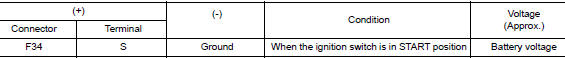
1.CHECK “S” CONNECTOR CIRCUIT
- Turn ignition switch OFF.
- Disconnect starter motor connector.
- Shift selector lever to “P” (Park) or “N” (Neutral) position.
- Check voltage between starter motor harness connector and ground.
Is the inspection result normal? YES >> “S” circuit is OK. Further inspection is necessary. Refer to STR-11, "Work Flow (With GR8-1200 NI)" or STR-15, "Work Flow (Without GR8-1200 NI)".
NO >> GO TO 2.
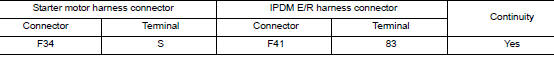
2.CHECK HARNESS CONTINUITY (OPEN CIRCUIT)
- Disconnect IPDM E/R connector.
- Check continuity between starter motor harness connector and the IPDM E/R harness connector
- Check continuity between starter motor terminal S and ground.

Is the inspection result normal? YES >> Further inspection is necessary. Refer to STR-11, "Work Flow (With GR8-1200 NI)" or STR-15, "Work Flow (Without GR8-1200 NI)".
NO >> Repair or replace the harness or connectors.
Symptom diagnosis
STARTING SYSTEM
Symptom Table
| Symptom | Reference |
| No normal cranking | Refer to STR-11, "Work Flow (With GR8-1200 NI)" or STR-15, "Work Flow (Without GR8-1200 NI)". |
| Starter motor does not rotate |
 B terminal circuit
Description
Terminal “B” is constantly supplied with battery power.
Diagnosis Procedure
Regarding Wiring Diagram information, refer to STR-7, "Wiring Diagram".
CAUTION:
Perform diag ...
 Removal and installation
STARTER MOTOR
Exploded View
REMOVAL
Transaxle assembly
Starter motor
Lower bolt
Upper bolt
Removal and Installation
REMOVAL
Remove battery tray. Refer to PG-77, & ...
Other materials:
Service data and specifications (sds)
Idle Speed
Condition
Specification
No load* (in P or N position)
650 ± 50 rpm
*: Under the following conditions
A/C switch: OFF
Electric load: OFF (Lights, heater fan & rear window defogger)
Steering wheel: Kept in straight-ahead position
...
P0340 CMP sensor (phase)
DTC Description
DTC DETECTION LOGIC
DTC No.
CONSULT screen terms
(Trouble diagnosis content)
DTC detecting cond
P0340
CMP SEN/CIRC-B1
(Camshaft position sensor ″A″ circuit bank
1 or single sensor)
The cylinder No. signal is not sent to ECM ...
Preparation
Special service tool
The actual shapes of techmate tools may differ from those of special service
tools illustrated here.
Tool number
(techmate no.)
Tool name
Description
St33061000
(j-8107-2)
drift
a: 38 mm (1.50 In) dia.
B: 28.5 Mm (1.122 In) dia.
Re ...
