Nissan Rogue Service Manual: B terminal circuit
Description
Terminal “B” is constantly supplied with battery power.
Diagnosis Procedure
Regarding Wiring Diagram information, refer to STR-7, "Wiring Diagram".
CAUTION: Perform diagnosis under the condition that the engine cannot start by the following procedure.
- Remove fuel pump fuse.
- Crank or start the engine (where possible) until the fuel pressure is released.
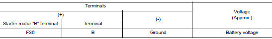
1.CHECK “B” TERMINAL CIRCUIT
- Turn ignition switch OFF.
- Check that starter motor ”B” terminal connection is clean and tight.
- Check voltage between starter motor ”B” terminal and ground.
Is the inspection result normal? YES >> GO TO 2.
NO >> Check harness between battery and starter motor for open circuit.
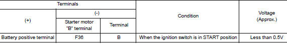
2.CHECK BATTERY CABLE CONNECTION STATUS (VOLTAGE DROP TEST)
- Shift selector lever to ”P” (Park) or ”N” (Neutral) position.
- Check voltage between battery positive terminal and starter motor ”B” terminal.
Is the inspection result normal? YES >> GO TO 3.
NO >> Check harness between the battery and starter motor for continuity.
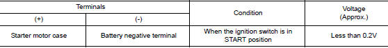
3.CHECK GROUND CIRCUIT STATUS (VOLTAGE DROP TEST)
- Shift selector lever to ”P” (Park) or ”N” (Neutral) position.
- Check voltage between starter motor case and battery negative terminal.
Is the inspection result normal?
YES >> “B” terminal circuit is OK. Further inspection is necessary. Refer to STR-11, "Work Flow (With GR8-1200 NI)" or STR-15, "Work Flow (Without GR8-1200 NI)".
NO >> Check the starter motor case to engine mounting for high resistance.

 S connector circuit
Description
The starter motor magnetic switch is supplied with power when the ignition
switch is turned to the START position
while the selector lever is in the P (Park) or N (Neutral) position.
...
Other materials:
System description
COMPONENT PARTS
POWER DOOR LOCK SYSTEM
POWER DOOR LOCK SYSTEM : Component Parts Location
No
Component
Function
1
BCM
Controls the door lock system.
Refer to BCS-79, "BODY CONTROL SYSTEM : Component Parts Location" for
detailed
instal ...
Symptom diagnosis
PUSH-BUTTON IGNITION SWITCH DOES NOT OPERATE
Description
Check that vehicle Operating Conditions are as listed in “Conditions of
Vehicle” below before starting Diagnosis
Procedure. Make sure to check each symptom in Diagnosis Procedure.
NOTE:
The engine start function, door lock functio ...
Steering column covers
Removal and Installation
REMOVAL
Release gap hider (1) pawls from the steering column upper
cover (2).
: Pawl
Remove steering column cover screws (A)
NOTE:
Rotate steering wheel to access steering column cover screws.
Release steering column upper cover (1) pawls u ...
