Nissan Rogue Service Manual: P0340 CMP sensor (phase)
DTC Description
DTC DETECTION LOGIC
| DTC No. | CONSULT screen terms (Trouble diagnosis content) | DTC detecting cond |
| P0340 | CMP SEN/CIRC-B1 (Camshaft position sensor ″A″ circuit bank 1 or single sensor) |
|
POSSIBLE CAUSE
- Harness or connectors (Camshaft position sensor circuit is open or shorted.)
- Camshaft position sensor
- Camshaft (Intake)
- Starter motor
- Starting system circuit
- Dead (Weak) battery
- Sensor power supply 2 circuit
FAIL-SAFE
Not applicable
DTC CONFIRMATION PROCEDURE
1.PRECONDITIONING
If DTC Confirmation Procedure has been previously conducted, always perform the following procedure before conducting the next test.
- Turn ignition switch OFF and wait at least 10 seconds.
- Turn ignition switch ON.
- Turn ignition switch OFF and wait at least 10 seconds.
TESTING CONDITION: Before performing the following procedure, confirm that battery voltage is more than 10.5 V with ignition switch ON.
>> GO TO 2.
2.PERFORM DTC CONFIRMATION PROCEDURE-1
- Start engine and let it idle for at least 5 seconds.
If engine does not start, crank engine for at least 2 seconds.
- Check 1st trip DTC.
Is 1st trip DTC detected? YES >> Proceed to EC-298, "Diagnosis Procedure".
NO >> GO TO 3.
3.PERFORM DTC CONFIRMATION PROCEDURE-2
- Maintaining engine speed at more than 800 rpm for at least 5 seconds.
- Check 1st trip DTC.
Is 1st trip DTC detected? YES >> Proceed to EC-298, "Diagnosis Procedure".
NO >> INSPECTION END
Diagnosis Procedure
1.CHECK STARTING SYSTEM
Turn ignition switch to START position.
Does the engine turn over? Does the starter motor operate?
YES >> GO TO 2.
NO >> Check starting system (Refer to STR-11, "Work Flow (With GR8-1200 NI)" or STR-15, "Work Flow (Without GR8-1200 NI)").
2.CHECK CAMSHAFT POSITION (CMP) SENSOR (PHASE) POWER SUPPLY
- Turn ignition switch OFF.
- Disconnect camshaft position (CMP) sensor (PHASE) harness connector.
- Turn ignition switch ON.
- Check the voltage between CMP sensor (PHASE) harness connector and ground.
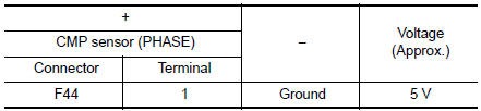
Is the inspection result normal? YES >> GO TO 4.
NO >> GO TO 3.
3.CHECK SENSOR POWER SUPPLY 2 CIRCUIT
Perform EC-484, "Diagnosis Procedure".
Is inspection result normal? YES >> Perform the trouble diagnosis for power supply circuit.
NO >> Repair or replace error-detected parts.
4.CHECK CMP SENSOR (PHASE) GROUND CIRCUIT
- Turn ignition switch OFF.
- Disconnect ECM harness connector.
- Check the continuity between CMP sensor (PHASE) harness connector and ECM harness connector.
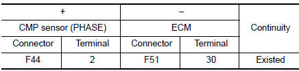
- Also check harness for short to power.
Is the inspection result normal? YES >> GO TO 5.
NO >> Repair or replace error-detected parts.
5.CHECK CMP SENSOR (PHASE) INPUT SIGNAL CIRCUIT
- Disconnect ECM harness connector.
- Check the continuity between CMP sensor (PHASE) harness connector and ECM harness connector
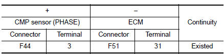
- Also check harness for short to ground and to power.
Is the inspection result normal? YES >> GO TO 6.
NO >> Repair or replace error-detected parts.
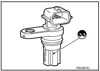
6.CHECK CAMSHAFT POSITION SENSOR (PHASE)
Check the camshaft position sensor (PHASE). Refer to EC-300, "Component Inspection (Camshaft position sensor)".
Is the inspection result normal? YES >> GO TO 7.
NO >> Replace camshaft position sensor (PHASE). Refer to EM-64, "Removal and Installation".
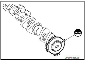
7.CHECK CAMSHAFT (INT)
Check the following.
- Accumulation of debris to the signal plate of camshaft rear end
- Chipping signal plate of camshaft rear end
Is the inspection result normal? YES >> GO TO 8.
NO >> Remove debris and clean the signal plate of camshaft rear end or replace camshaft. Refer to EM-64, "Removal and Installation".
8.CHECK INTERMITTENT INCIDENT
Refer to GI-41, "Intermittent Incident".
>> INSPECTION END
Component Inspection (Camshaft position sensor)
1.CHECK CAMSHAFT POSITION SENSOR (PHASE)-1
- Turn ignition switch OFF.
- Loosen the fixing bolt of the sensor.
- Disconnect camshaft position sensor (PHASE) harness connector.
- Remove the sensor.
- Visually check the sensor for chipping.
Is the inspection result normal? YES >> GO TO 2.
NO >> Replace camshaft position sensor (PHASE).
2.CHECK CAMSHAFT POSITION SENSOR (PHASE)-2
Check the resistance camshaft position sensor (PHASE) terminals as per the following.
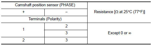
Is the inspection result normal? YES >> INSPECTION END
NO >> Replace camshaft position sensor (PHASE). Refer to EM-64, "Removal and Installation".
 P0335 CKP sensor (POS)
DTC Description
DTC DETECTION LOGIC
DTC No.
CONSULT screen terms
(Trouble diagnosis content)
DTC detecting conditio
P0335
CKP SEN/CIRCUIT
(Crankshaft position sensor & ...
 P0420 three way catalyst function
DTC Description
DTC DETECTION LOGIC
The ECM monitors the switching frequency ratio of air fuel ratio (A/F)
sensor 1 and heated oxygen sensor 2.
A three way catalyst (manifold) with high oxygen s ...
Other materials:
Steering wheel
Exploded View
Steering wheel
Removal and Installation
REMOVAL
Set the front wheels and tires in the straight-ahead position.
Remove driver air bag module. Refer to SR-12, "Removal and
Installation"
Remove steering wheel bolt.
Disconnect harn ...
Fuel tank
FWD
FWD : Exploded View
Fuel filler cap
Grommet
Fuel filler tube
Cover
Clamp
Fuel filler hose
Clamp
Vent hose
Fuel tank protector
Fuel tank strap (LH)
Fuel tank strap (RH)
Fuel tank
T ...
P0604 ECM
DTC Description
DTC DETECTION LOGIC
DTC No.
CONSULT screen terms
(Trouble diagnosis content)
DTC detecting condition
P0604
ECM
[Internal control module random access
memory (RAM) error]
Malfunction in the internal RAM of ECM.
POSSIBLE CAUSE
ECM
FAIL-SAF ...
