Nissan Rogue Service Manual: Driver air bag module
Exploded View
- Steering wheel
- Driver air bag module
Removal and Installation
WARNING:
- Before servicing the SRS, turn ignition switch OFF, disconnect both battery terminals then wait at least three minutes.
- Always work from the side of driver air bag module. Do not work in front of it.
- Do not use the air tools or electric tools for servicing.
REMOVAL
- Disconnect negative and positive battery terminals, then wait at least three minutes. Refer to PG-77, "Removal and Installation".
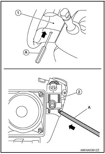
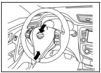
- Release driver air bag module hooks.
- Locate the access hole on RH side of steering wheel rear finisher
(1) and insert (
 ) a 5.0 mm
(0.20 in) diameter suitable tool
(A).
) a 5.0 mm
(0.20 in) diameter suitable tool
(A). - Push suitable tool (A) inward (
 ) and make sure the tool contacts
the spring (2) as shown. Push on the upper right of the
driver air bag module while pressing on the spring to release the
driver air bag module hook (RH). Repeat procedure for driver air
bag module hook (LH).
) and make sure the tool contacts
the spring (2) as shown. Push on the upper right of the
driver air bag module while pressing on the spring to release the
driver air bag module hook (RH). Repeat procedure for driver air
bag module hook (LH).NOTE: Driver air bag module removed for clarity.
- Lift driver air bag module as shown, then disconnect harness connectors from the driver air bag module.
CAUTION:
- For installing/removing the driver air bag module harness connector, insert thin screwdriver wrapped in tape into notch, lift lock and remove the connector.
- Install the connector with lock raised, and push lock into the connector.
- After installing the connector, check that the lock is pushed securely into it.
- Remove the driver air bag module.
CAUTION:
- Always place the driver air bag module with pad side facing upward.
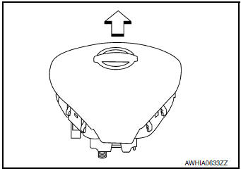
 : Upward
- Do not strike or impact the driver air bag module.
- Replace the driver air bag module if it has been dropped or sustained an impact.
- Do not insert any foreign objects (screwdriver, etc.) into the driver air bag module.
- Do not disassemble the driver air bag module.
- Do not expose the driver air bag module to temperatures exceeding 93°C (199°F).
- Do not allow oil, grease, detergent, or water to come in contact with the driver air bag module.
INSTALLATION
Installation is in the reverse order of removal.
CAUTION:
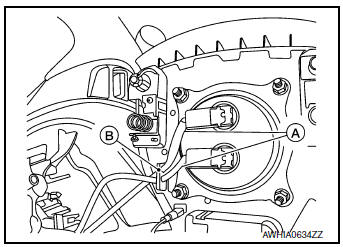
- Always connect the driver air bag module harnesses (A) and route through the hook (B) as shown.
- If driver air bag module is being replaced due to deployment, the
spiral cable must also be replaced.
Refer to SR-15, "Removal and Installation".
- Do not pinch or damage the harnesses while installing.
- If a malfunction is indicated by the air bag warning lamp after repair or replacement of the malfunctioning parts, perform the SRS Final Check. Refer to SRC-18, "Trouble Diagnosis with CONSULT".
- After installation is complete, check that no system malfunction is detected causing the air bag warning lamp to illuminate.

 Spiral cable
Exploded View
Combination switch
Steering angle sensor
Spiral cabl
Removal and Installation
WARNING:
Before servicing the SRS, turn ignition switch OFF, disconnect
both ...
Other materials:
Rear wiper motor circuit
Component Function Check
1. CHECK REAR WIPER ON OPERATION
CONSULT ACTIVE TEST
Select "RR WIPER" of BCM active test item.
While operating the test item, check rear wiper operation.
ON : Rear wiper ON operation
OFF : Stop the rear wiper.
Is rear wiper operation norm ...
Electrical load signal
Description
The electrical load signal (Headlamp switch signal, rear window defogger
switch signal, etc.) is transferred via
the CAN communication.
Component Function Check
1.CHECK REAR WINDOW DEFOGGER SWITCH FUNCTION
Turn ignition switch ON.
Connect CONSULT and select “DAT ...
Removal and installation
FRONT WHEEL HUB
Exploded View
Disc brake rotor
Nut retainer
Cotter pin
Wheel stud
Steering knuckle
Splash guard
Wheel hub and bearing
Wheel hub lock nut
Removal and Installation
REMOVAL
Remove front wheel and tire using power tool. Refe ...
