Nissan Rogue Service Manual: Rear wiper motor circuit
Component Function Check
1. CHECK REAR WIPER ON OPERATION
 CONSULT ACTIVE TEST
- Select "RR WIPER" of BCM active test item.
- While operating the test item, check rear wiper operation.
ON : Rear wiper ON operation
OFF : Stop the rear wiper.
Is rear wiper operation normal? YES >> Rear wiper motor circuit is normal.
NO >> Refer to WW-47, "Diagnosis Procedure".
Diagnosis Procedure
Regarding Wiring Diagram information, refer to WW-28, "Wiring Diagram".
1. CHECK REAR WIPER MOTOR OUTPUT VOLTAGE
CONSULT ACTIVE TEST
- Turn the ignition switch OFF.
- Disconnect rear wiper motor.
- Turn the ignition switch ON.
- Select RR WIPER of BCM active test item.
- While operating the test item, check voltage between BCM harness connector and ground.
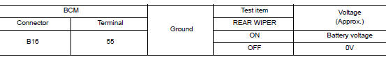
Is the inspection result normal? YES >> GO TO 2.
NO >> GO TO 3.
2. CHECK REAR WIPER MOTOR GROUND CIRCUIT
- Turn the ignition switch OFF.
- Check continuity between rear wiper motor harness connector and ground.
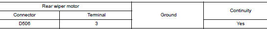
Is the inspection result normal? YES >> Replace rear wiper motor. Refer to WW-71, "Removal and Installation".
NO >> Repair or replace harness.
3. CHECK REAR WIPER MOTOR OPEN CIRCUIT
Check continuity between BCM harness connector and rear wiper motor harness connector.
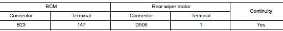
Is the inspection result normal? YES >> GO TO 4.
NO >> Repair or replace harness.
4. CHECK REAR WIPER MOTOR SHORT CIRCUIT
Check continuity between BCM harness connector and ground.
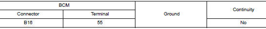
Is the inspection result normal? YES >> Repair or replace harness.
NO >> Replace BCM. Refer to BCS-75, "Removal and Installation" (with Intelligent Key system) or BCS- 135, "Removal and Installation" (without Intelligent Key system).
 Washer switch
Description
Washer switch is integrated with the combination switch.
Combination switch (wiper and washer switch) switches polarity
between front washer operating and rear
washer oper ...
 Rear wiper auto stop signal circuit
Component Function Check
1. CHECK REAR WIPER (AUTO STOP) OPERATION
CONSULT DATA MONITOR
Select WIPER of BCM data monitor item.
Operate the rear wiper.
Check that RR WIPER ...
Other materials:
C1142 press sensor
DTC Logic
DTC DETECTION LOGIC
DTC
Display Item
Malfunction detected condition
Possible causes
C1142
PRESS SEN CIRCUIT
When a malfunction is detected in master cylinder
pressure sensor
Stop lamp switch system
ABS actuator and electric unit
...
Basic inspection
DIAGNOSIS AND REPAIR WORKFLOW
Work Flow
WORK FLOW
DETAILED FLOW
1. REVIEW CUSTOMER COMPLAINT
Review customer complaint. Try to obtain detailed information about the
conditions when the symptom occurs.
>> GO TO 2.
2. VERIFY THE SYMPTOM
Verify the symptom by performing an operation ...
Symptom diagnosis
THE SPORT MODE INDICATOR LAMP DOES NOT TURN ON
Description
The SPORT mode indicator lamp does not turn ON when the SPORT mode switch is
operated.
Diagnosis Procedure
1.CHECK SPORT MODE INDICATOR LAMP FUNCTION
Perform combination meter self-diagnosis mode and check test order 10. Refer
to MW ...
