Nissan Rogue Service Manual: Component parts
Component Parts Location
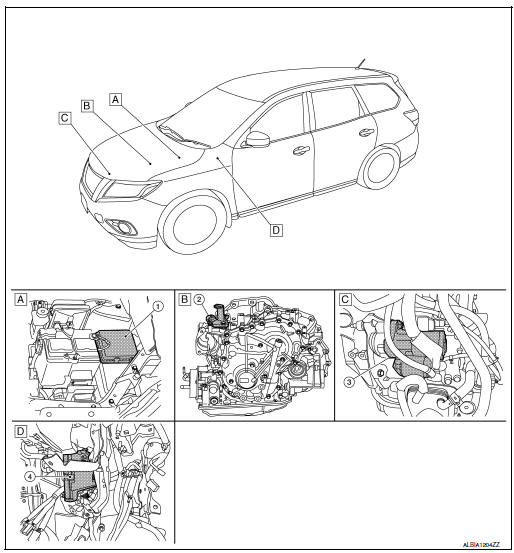
- Engine room (RH)
- View with transmission removed
- View with engine and transmission removed
- Behind instrument panel (LH)
| No. | Component part | Description |
| 1 | IPDM E/R | CPU inside IPDM E/R operates the starter relay when the ignition switch is in the start position. |
| 2 | Transmission range switch | Transmission range switch supplies power to the starter relay and starter control relay inside the IPDM E/R when the selector lever is shifted to the P (Park) or N (Neutral) position. |
| 3 | Starter motor | The starter motor plunger closes and the motor is supplied with battery power, which in turn cranks the engine, when the S terminals supplied with electric power. |
| 4 | BCM | BCM controls the starter relay inside IPDM E/R. |

 System
System Description
The starter motor plunger closes and provides a closed circuit between the
battery and the starter motor. The
starter motor is grounded to the cylinder block. With power and gro ...
Other materials:
C1770, C1771, C1772, C1773 G sensor
DTC Description
DTC DETECTION LOGIC
DTC
Display Item
Malfunction Detected Condition
Possible Causes
C1770
G SENSOR FL
(G sensor front left)
Malfunction in the G sensor data from front left wheel sensor.
Tire pressure sensor
Tire pressure rece ...
Removal and installation
FRONT COMBINATION LAMP
Exploded View
Front fender
Front combination lamp
Clip
Removal and Installation
REMOVAL
Remove front bumper fascia. Refer to EXT-17, "Removal and
Installation".
Remove front combination lamp bolts and clip.
Pull front c ...
Removal and installation
REAR PROPELLER SHAFT
Exploded View
Center bearing mounting bracket
(upper)
Clip
Propeller shaft assembly
Center bearing mounting bracket
(lower)
: Vehicle front
: N·m (kg-m, ft-lb)
: Always replace after every
disassembly.
Removal and Installation
REMOVAL
Shif ...
