Nissan Rogue Service Manual: Removal and installation
FRONT COMBINATION LAMP
Exploded View
- Front fender
- Front combination lamp
 Clip
Clip
Removal and Installation
REMOVAL
- Remove front bumper fascia. Refer to EXT-17, "Removal and Installation".
- Remove front combination lamp bolts and clip.
- Pull front combination lamp forward.
- Disconnect the harness connectors from the front combination lamp and remove.
INSTALLATION
Installation is in the reverse order of removal.
NOTE: After installation, perform headlamp aiming adjustment. Refer to EXL-114, "Inspection".
Bulb Replacement
HEADLAMP (LOW BEAM) BULB
The headlamp (low beam) bulb is not serviced separately. Refer to EXL-119, "Removal and Installation".
HEADLAMP (HIGH BEAM) BULB
The headlamp (high beam) bulb is not serviced separately. Refer to EXL-119, "Removal and Installation".
PARKING (SIDE MARKER) LAMP BULB
The parking lamp (side marker) bulb is not serviced separately. Refer to EXL-119, "Removal and Installation".
TURN SIGNAL LAMP BULB
Removal
- Rotate bulb socket counterclockwise and remove from the front combination lamp.
- Remove the bulb from bulb socket.
Installation
Installation is in the reverse order of removal.
CAUTION: After installing the bulb, install the bulb socket securely for watertightness.
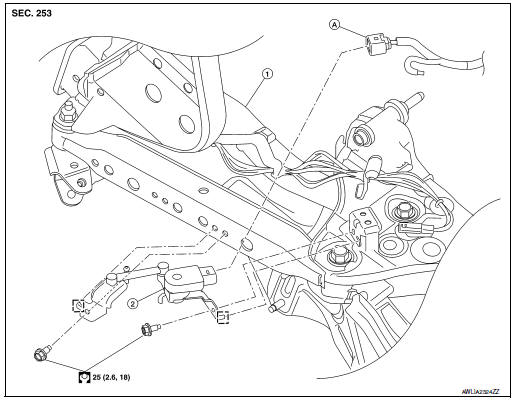
HEIGHT SENSOR
Exploded View
- Front suspension member
- Front height sensor
- Harness connector
 Locator
Removal and Installation - Front Height Sensor
REMOVAL
- Disconnect the harness connector from the front height sensor.
- Remove the nuts and the front height sensor.
INSTALLATION
Installation is in the reverse order of removal.
After installation, perform height sensor initialization. Refer to EXL-222, "SENSOR INITIALIZE : Description".
Exploded View
- Rear suspension member
- Rear height sensor
- Harness connector
Locator
Removal and Installation - Rear Height Sensor
REMOVAL
- Disconnect the harness connector from the rear height sensor.
- Remove the bolts and rear height sensor.
INSTALLATION
Installation is in the reverse order of removal.
After installation, perform height sensor initialization. Refer to EXL-222, "SENSOR INITIALIZE : Description".
FOG LAMP
Exploded View
- Front bumper fascia
- Fog lamp
- Fog lamp bulb
 Front
Front
Removal and Installation
REMOVAL
- Partially remove front fender protector. Refer to EXT-28, "FENDER PROTECTOR : Exploded View".
- Disconnect the harness connector from the fog lamp.
- Remove fog lamp bolts and fog lamp.
INSTALLATION
Installation in the reverse order of removal.
NOTE: After installation, perform fog lamp aiming adjustment. Refer to EXL-117, "Aiming Adjustment Procedure".
Bulb Replacement
WARNING: Do not touch bulb by hand while it is lit or right after being turned off. Burning may result.
CAUTION:
- Do not touch the glass surface of the bulb with bare hands or allow oil or grease to get on it to prevent damage to the bulb.
- Do not leave bulb out of lamp reflector for a long time because dust, moisture smoke, etc. may affect the performance of lamp. When replacing bulb, be sure to replace it with new one.
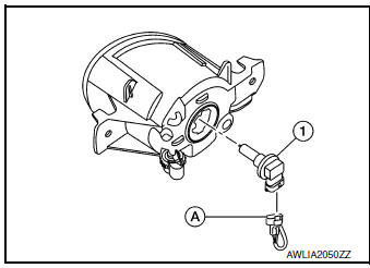
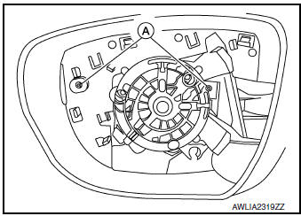
REMOVAL
- Partially remove front fender protector. Refer to EXT-28, "FENDER PROTECTOR : Exploded View".
- Disconnect the harness connector from the fog lamp (A).
- Rotate bulb (1) counterclockwise and remove.
INSTALLATION
Installation is in the reverse order of removal.
CAUTION: After installing the bulb, install the bulb socket securely for watertightness.
OPTICAL SENSOR
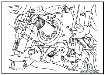
Removal and Installation
REMOVAL
- Release the optical sensor (2) from defroster grille (1) using a suitable tool.
- Disconnect the harness connector (A) from the optical sensor (2) and remove.
INSTALLATION
Installation is in the reverse order of removal.
COMBINATION SWITCH
Exploded View
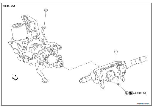
- Combination switch
- Steering column
- Screw
 Front
Front
Removal and Installation
REMOVAL
- Remove the steering angle sensor. Refer to BRC-139, "Removal and Installation".
- Disconnect harness connector from combination switch.
- Remove screw (A) and combination switch (1).
INSTALLATION
Installation is in the reverse order of removal.
HAZARD SWITCH
Exploded View
- Center ventilator grille
- Hazard switch
 Pawl
Pawl
Removal and Installation
REMOVAL
- Remove center ventilator grille. Refer to VTL-13, "CENTER VENTILATOR GRILLE : Removal and Installation".
- Release the pawls and remove the hazard switch.
INSTALLATION
Installation is in the reverse order of removal.
SIDE TURN SIGNAL LAMP
Removal and Installation
REMOVAL
- Remove door mirror rear finisher. Refer to MIR-25, "Removal and Installation".
- Remove door mirror glass. Refer to MIR-24, "Removal and Installation".
- Remove the screws (A) and reposition side turn signal lamp.
- Disconnect the harness connector from the side turn signal lamp and remove.
INSTALLATION
Installation is in the reverse order of removal.
Bulb Replacement
The side turn signal lamp bulb is not serviced separately. Refer to EXL-126, "Removal and Installation".
REAR COMBINATION LAMP
Exploded View
- Rear combination lamp
- Grommet
- Clip
Removal and Installation
REMOVAL
- Remove side air spoiler. Refer to EXT-48, "Removal and Installation".
- Remove rear combination lamp bolts.
- Pull rear combination lamp rearward to release from clip and locators.
- Disconnect the harness connector from the rear combination lamp and remove.
INSTALLATION
Installation is in the reverse order of removal.
Bulb Replacement
WARNING: Do not touch bulb with bare hand while it is lit or right after being turned off. Burning may result.
CAUTION:
- Do not touch the glass surface of the bulb with bare hands or allow oil or grease to get on it to prevent damage to the bulb.
- Do not leave bulb out of lamp reflector for a long time because dust, moisture smoke, etc. may affect the performance of lamp. When replacing bulb, be sure to replace it with new one.
STOP LAMP BULB
Removal
- Remove rear combination lamp. Refer to EXL-127, "Removal and Installation".
- Rotate stop lamp bulb socket counterclockwise and remove.
- Remove stop lamp bulb from bulb socket.
Installation
Installation is in the reverse order of removal.
CAUTION: After installing the bulb, install bulb socket securely for watertightness.
TAIL LAMP BULB
Removal
- Remove rear combination lamp. Refer to EXL-127, "Removal and Installation".
- Rotate tail lamp bulb socket counterclockwise and remove.
- Remove tail lamp bulb from bulb socket.
Installation
Installation is in the reverse order of removal.
CAUTION: After installing the bulb, install bulb socket securely for watertightness.
TURN SIGNAL LAMP BULB
Removal
- Remove rear combination lamp. Refer to EXL-127, "Removal and Installation".
- Rotate turn signal lamp bulb socket counterclockwise and remove.
- Remove turn signal lamp bulb from bulb socket.
Installation
Installation is in the reverse order of removal.
CAUTION: After installing the bulb, install bulb socket securely for watertightness.
HIGH-MOUNTED STOP LAMP
Exploded View
- High-mounted stop lamp
- Back door
 Stud
Stud
Removal and Installation
REMOVAL
- Remove access cover using a suitable tool. Refer to INT-38, "Exploded View".
- Remove high-mounted stop lamp nuts.
- Disconnect the harness connector from high-mounted stop lamp and remove.
INSTALLATION
Installation is in the reverse order of removal.
Bulb Replacement
HIGH-MOUNTED STOP LAMP BULB
The high-mounted stop lamp bulb is not serviced separately. Refer to EXL-129, "Removal and Installation".
BACK-UP LAMP ASSEMBLY
Exploded View
- Back-up lamp assembly
- Back door
 Clip
Clip
 Stud
Stud
Removal and Installation
REMOVAL
- Remove back door finisher. Refer to INT-38, "Removal and Installation".
- Remove back-up lamp assembly nuts.
- Pull back-up lamp assembly rearward, disconnect the harness connector and remove.
INSTALLATION
Installation is in the reverse order of removal.
Bulb Replacement
WARNING: Do not touch bulb with bare hand while it is lit or right after being turned off. Burning may result.
CAUTION:
- Do not touch the glass surface of the bulb with bare hands or allow oil or grease to get on it to prevent damage to the bulb.
- Do not leave bulb out of lamp reflector for a long time because dust, moisture smoke, etc. may affect the performance of lamp. When replacing bulb, be sure to replace it with new one.
TAIL LAMP BULB
Removal
- Remove back-up lamp assembly. Refer to EXL-130, "Removal and Installation".
- Rotate tail lamp bulb socket counterclockwise and remove.
- Remove tail lamp bulb from bulb socket.
Installation
Installation is in the reverse order of removal.
CAUTION: After installing the bulb, install bulb socket securely for watertightness.
BACK-UP LAMP BULB
Removal
- Remove back-up lamp assembly. Refer to EXL-130, "Removal and Installation".
- Rotate back-up lamp bulb socket counterclockwise and remove.
- Remove back-up lamp bulb from bulb socket.
Installation
Installation is in the reverse order of removal.
CAUTION: After installing the bulb, install bulb socket securely for watertightness.
LICENSE PLATE LAMP
Exploded View
- License plate lamp bulb
- License plate lamp seal
- License plate lamp
- License plate lamp assembly
- License plate lamp bulb socket
Removal and Installation
REMOVAL
- Release the license lamp finisher. Refer to EXT-50, "Exploded View".
- Remove the screw (A) (LH or RH) and pull license plate lamp (1) (LH or RH) rearward.
- Disconnect the harness connector from the license plate lamp and remove.
INSTALLATION
Installation is in the reverse order of removal.
Bulb Replacement
WARNING: Do not touch bulb with your hand while it is on or right after being turned off. Burning may result.
CAUTION:
- Do not touch the glass surface of the bulb with bare hands or allow oil or grease to get on it to prevent damage to the bulb.
- Do not leave bulb out of lamp reflector for a long time because dust, moisture smoke, etc. may affect the performance of lamp. When replacing bulb, be sure to replace it with new one.
REMOVAL
- Remove license plate lamp. Refer to EXL-283, "Removal and Installation".
- Rotate license plate lamp bulb socket counterclockwise and remove.
- Remove license plate lamp bulb from bulb socket.
INSTALLATION
Installation is in the reverse order of removal.
CAUTION: After installing the bulb, install the bulb socket securely for watertightness.
 Periodic maintenance
HEADLAMP AIMING ADJUSTMENT
Inspection
PREPARATION BEFORE ADJUSTING
Before performing aiming adjustment, check the following:
Make sure all tires are inflated to correct pressure.
...
 Unit disassembly and assembly
FRONT COMBINATION LAMP
Exploded View
Front combination lamp
Turn signal lamp bulb socket
Disassembly and Assembly
DISASSEMBLY
Remove front combination lamp. Refer to EXL-268, ...
Other materials:
C1111 pump motor
DTC Logic
DTC DETECTION LOGIC
DTC
Display Item
Malfunction detected condition
Possible causes
C1111
PUMP MOTOR
When a malfunction is detected in motor or motor relay.
Harness or connector
ABS actuator and electric unit
(control unit)
&nb ...
P0137 HO2S2
DTC Description
DTC DETECTION LOGIC
The heated oxygen sensor 2 has a much longer switching time
between rich and lean than the air fuel ratio (A/F) sensor 1. The oxygen
storage capacity of the three way catalyst (manifold) causes the
longer switching time. To judge the malfunctions of heated ox ...
Unit disassembly and assembly
FRONT COMBINATION LAMP
Exploded View
Front combination lamp
Turn signal lamp bulb socket
Disassembly and Assembly
DISASSEMBLY
Remove front combination lamp. Refer to EXL-268, "Removal and
Installation".
Rotate the turn signal lamp bulb socket counterclo ...
