Nissan Rogue Service Manual: C1111 pump motor
DTC Logic
DTC DETECTION LOGIC
| DTC | Display Item | Malfunction detected condition | Possible causes |
| C1111 | PUMP MOTOR | When a malfunction is detected in motor or motor relay. |
|
DTC CONFIRMATION PROCEDURE
1.CHECK SELF-DIAGNOSTIC RESULT
 With CONSULT.
- Turn ignition switch OFF.
- Depress brake pedal 20 times or more.
- Start the engine and wait for 3 minutes or more.
- Perform self-diagnostic result.
Is DTC C1111 detected? YES >> Proceed to diagnosis procedure. Refer to BRC-82, "Diagnosis Procedure".
NO >> Inspection End.
Diagnosis Procedure
Regarding Wiring Diagram information, refer to BRC-57, "Wiring Diagram".
1.CONNECTOR INSPECTION
- Turn ignition switch OFF.
- Disconnect ABS actuator and electric unit (control unit) connectors.
- Check connectors and terminals for deformation, disconnection, looseness or damage.
Is the inspection result normal? YES >> GO TO 2.
NO >> Repair or replace as necessary.
2.CHECK ABS MOTOR AND MOTOR RELAY BATTERY POWER SUPPLY
Check voltage between ABS actuator and electric unit (control unit) connector E125 terminal 1 and ground.
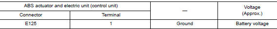
Is the inspection result normal? YES >> GO TO 3.
NO >> Repair or replace malfunctioning components.
3.CHECK ABS ACTUATOR AND ELECTRIC UNIT (CONTROL UNIT) GROUND CIRCUIT
Check continuity between ABS actuator and electric unit (control unit) connector E125 terminals 13, 38 and ground.
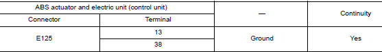
Is the inspection result normal? YES >> Replace ABS actuator and electric unit (control unit). Refer to BRC-136, "Removal and Installation" NO >> Repair or replace harness.
 C1109 power and ground system
DTC Logic
DTC DETECTION LOGIC
DTC
Display Item
Malfunction detected condition
Possible causes
C1109
BATTERY VOLTAGE
[ABNORMAL]
When ignition voltage is 10 ...
 C1113, C1145, C1146 yaw rate/side/decel G sensor
DTC
Display Item
Malfunction detected condition
Possible causes
C1113
G SENSOR
When a malfunction is detected in longitudinal G sensor
signal.
Harness or ...
Other materials:
Preparation
Special Service Tools
The actual shape of the tools may differ from those illustrated here.
Tool number
(TechMate No.)
Tool name
Description
KV10111100
(J-37228)
Seal cutter
Removing oil pan (lower) etc.
Commercial Service Tools
T ...
Symptom diagnosis
CHASSIS CONTROL
Active Engine Brake
NOTE:
For the operational conditions of Active Engine Brake, refer to
DAS-175, "System Description - Active
Engine Brake".
Perform the self-diagnosis with CONSULT before the symptom
diagnosis. Perform the trouble diagnosis if
...
Connector Symbols
Most of connector symbols in wiring diagrams are shown from the terminal
side.
Connector symbols shown from the terminal side are enclosed by
a single line and followed by the direction mark.
Connector symbols shown from the harness side are enclosed by
a double line and foll ...
