Nissan Rogue Service Manual: C1109 power and ground system
DTC Logic
DTC DETECTION LOGIC
| DTC | Display Item | Malfunction detected condition | Possible causes |
| C1109 | BATTERY VOLTAGE [ABNORMAL] |
|
|
DTC CONFIRMATION PROCEDURE
1.CHECK SELF-DIAGNOSTIC RESULT
 With CONSULT.
- Turn the ignition switch OFF to ON.
- Perform self-diagnostic result.
Is DTC C1109 detected? YES >> Proceed to diagnosis procedure. Refer to BRC-80, "Diagnosis Procedure".
NO >> Inspection End.
Diagnosis Procedure
Regarding Wiring Diagram information, refer to BRC-57, "Wiring Diagram".
1.CONNECTOR INSPECTION
- Turn ignition switch OFF.
- Disconnect ABS actuator and electric unit (control unit) connectors.
- Check connectors and terminals for deformation, disconnection, looseness or damage.
Is the inspection result normal? YES >> GO TO 2.
NO >> Repair or replace as necessary.
2.CHECK ABS ACTUATOR AND ELECTRIC UNIT (CONTROL UNIT) IGNITION POWER SUPPLY CIRCUIT
Check voltage between ABS actuator and electric unit (control unit) connector E125 terminal 28 and ground.
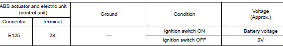
Is the inspection result normal? YES >> GO TO 3.
NO >> Repair or replace malfunctioning components.
3.CHECK ABS ACTUATOR AND ELECTRIC UNIT (CONTROL UNIT) BATTERY POWER SUPPLY CIRCUIT
Check voltage between ABS actuator and electric unit (control unit) connector E125 terminals 1, 25 and ground.

Is the inspection result normal? YES >> GO TO 4.
NO >> Repair or replace malfunctioning components.
4.CHECK ABS ACTUATOR AND ELECTRIC UNIT (CONTROL UNIT) GROUND CIRCUIT
- Turn ignition switch OFF.
- Check continuity between ABS actuator and electric unit (control unit) connector E125 terminals 13, 38 and ground.
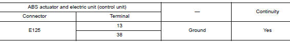
Is the inspection result normal? YES >> Replace ABS actuator and electric unit (control unit). Refer to BRC-136, "Removal and Installation".
NO >> Repair or replace malfunctioning components.
 C1105, C1106, C1107, C1108 wheel sensor
DTC Logic
DTC DETECTION LOGIC
DTC
Display Item
Malfunction detected condition
Possible causes
C1105
RR RH SENSOR-2
When distance between rear ...
 C1111 pump motor
DTC Logic
DTC DETECTION LOGIC
DTC
Display Item
Malfunction detected condition
Possible causes
C1111
PUMP MOTOR
When a malfunction is detected in motor or motor relay.
...
Other materials:
Indicator lights
For additional information on warnings and indicators,
refer to “Vehicle information display” in
this section.
All-Wheel Drive
(AWD) AUTO indicator light (if so equipped)
When the ignition switch is in the “ON” position,
the All-Wheel Drive (AWD) AUTO indicator light
illuminates.
...
Precaution
Precaution for Supplemental Restraint System (SRS) "AIR BAG" and "SEAT
BELT
PRE-TENSIONER"
The Supplemental Restraint System such as “AIR BAG” and “SEAT BELT
PRE-TENSIONER”, used along
with a front seat belt, helps to reduce the risk or severity of injury to the
...
How to select piston and bearing
DESCRIPTION
Selection points
Selection parts
Selection items
Selection methods
Between cylinder block to
crankshaft
Main bearing
Main bearing grade (bearing
thickness)
Determined by match of cylinder
block bearing housing
grade (inner diameter of housin ...
