Nissan Rogue Service Manual: Removal and installation
REAR PROPELLER SHAFT
Exploded View
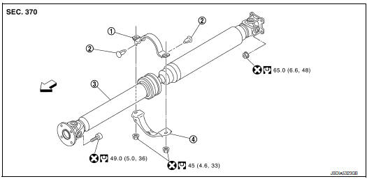
- Center bearing mounting bracket (upper)
- Clip
- Propeller shaft assembly
- Center bearing mounting bracket (lower)
 : Vehicle front
 : N·m (kg-m, ft-lb)
 : Always replace after every
disassembly.
: Always replace after every
disassembly.
Removal and Installation
REMOVAL
- Shift the transaxle to the neutral position, and then release the parking brake.
- Remove muffler assembly. Refer to EX-5, "Removal and Installation".
- Put matching marks onto propeller shaft flange yoke and final drive and transfer companion flanges.
CAUTION: For matching marks, use paint. Do not damage propeller shaft flange yoke and transfer companion flange.
- Loosen nuts of center bearing brackets (upper/lower).
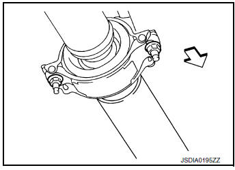
 : Front
CAUTION: Tighten nuts temporarily.
- Remove propeller shaft assembly bolts and nuts.
- Remove center bearing bracket nuts.
- Remove propeller shaft assembly.
CAUTION: If constant velocity joint was bent during propeller shaft assembly removal, installation, or transportation, its boot may be damaged. Wrap boot interference area to metal part with shop cloth or rubber to protect boot from breakage.
- Remove clips and center bearing bracket (upper/lower).
INSTALLATION
Installation is in the reverse order of removal.
- When removing propeller shaft from final drive assembly (electric controlled coupling), replace stud bolts of electric controlled coupling.
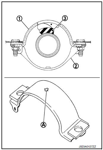
- Install center bearing bracket (upper) (1) with its arrow mark (A) facing forward.
- Adjust position of center bearing bracket (upper), center bearing bracket (lower) (2) sliding back and forth to prevent play in thrust direction of center bearing insulator (3). Install center bearing bracket (upper/lower) to vehicle.
- Align matching marks to install propeller shaft assembly to final drive and transfer companion flanges.
- Perform inspection after installation. Refer to DLN-101, "Inspection".
- After tightening the bolts and nuts to the specified torque, make sure that the bolts (3) on the flange side is tightened as shown in the figure.
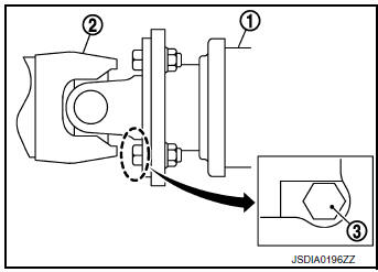
(1) : Final drive assembly
(2) : Propeller shaft assembly
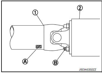
- If propeller shaft assembly or final drive assembly (electric controlled coupling) has been replaced, connect them as follows:
- Install propeller shaft (1) while aligning its matching marks (A) on propeller shaft with matching mark (B) on electric controlled coupling and join them as close as possible.
Inspection
INSPECTION AFTER REMOVAL
Appearance
Check propeller shaft tube surface for dents or cracks. If malfunction is detected, replace propeller shaft assembly.
Propeller Shaft Runout
Check propeller shaft runout at measuring points with a dial indicator.
If runout exceeds specifications, replace propeller shaft assembly.
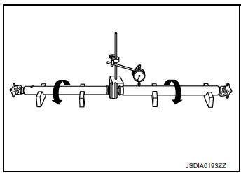
Propeller shaft runout : Refer to DLN-103, "Propeller Shaft Runout".
- Propeller shaft runout measuring point (Point “
 ”).
”).
 : Front side
Dimension
A : 541.5 mm (21.32 in)
B : 488.7 mm (19.24 in)
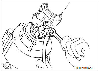
Journal Axial Play
As shown in the figure, while fixing yoke on one side, check axial play of joint. If it is outside the standard, replace propeller shaft assembly.
Journal axial play : Refer to DLN-103, "Journal Axial Play".
CAUTION: Never disassemble joints.
Center Bearing
Check center bearing for noise and damage. If malfunction is detected, replace propeller shaft assembly.
CAUTION: Never disassemble center bearing.
INSPECTION AFTER INSTALLATION
After assembly, perform a driving test to check propeller shaft vibration. If vibration occurred, separate propeller shaft from final drive. Reinstall propeller shaft by changing the phase between electric controlled coupling stud bolt and propeller shaft by the one bolt hole at a time. Then perform driving test and check propeller shaft vibration again at each point.
 Periodic maintenance
REAR PROPELLER SHAFT
Inspection
APPEARANCE AND NOISE
Check the propeller shaft tube surface for dents or cracks. If
malfunction is detected, replace propeller shaft
assembly.
...
 Service data and specifications (SDS)
General Specifications
Propeller Shaft Runout
Journal Axial Play
...
Other materials:
Cooling fan
Component Function Check
1.CHECK COOLING FAN FUNCTION
With CONSULT
Turn ignition switch ON.
Perform “COOLING FAN (DUAL)” in “ACTIVE TEST” mode of “IPDM E/R”
using CONSULT.
Touch “LOW”, “HI” on the CONSULT screen.
Check that cooling fan opera ...
SRS air bag warning lamp does not turn on
AIR BAG Warning Lamp Does Not Turn On
1.CHECK METER FUSE
Check the 10A fuse [No. 13, located in the fuse block (J/B)].
Is the fuse blown?
YES >> GO TO 2.
NO >> GO TO 3.
2.REPLACE METER FUSE AND CHECK AGAIN
Replace 10A fuse [No. 13, located in the fuse block (J/B)] and turn ign ...
Wiring diagram
CAN SYSTEM
Wiring Diagram - CAN SYSTEM -
...
