Nissan Rogue Service Manual: Wiring diagram
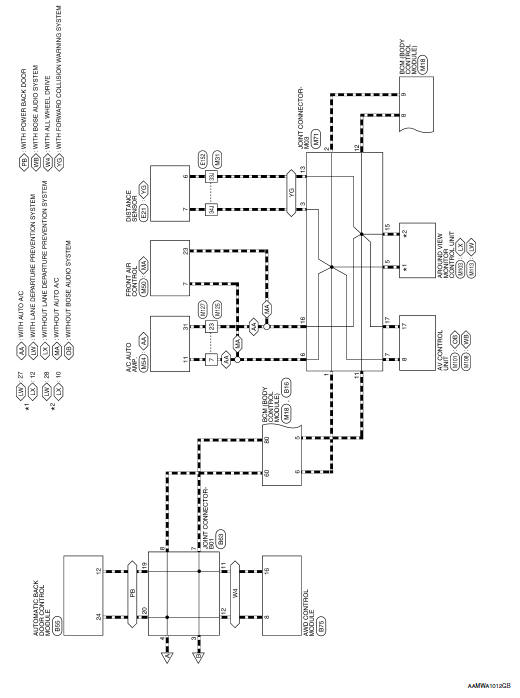
CAN SYSTEM
Wiring Diagram - CAN SYSTEM -
 System description
COMPONENT PARTS
Component Parts Location
Air bag diagnosis sensor unit
AV control unit
Around view monitor control unit
Chassis control module
ABS actuator and electric unit (contr ...
 Basic inspection
DIAGNOSIS AND REPAIR WORKFLOW
Interview Sheet
...
Other materials:
P0117, P0118 ECT sensor
DTC Description
DTC DETECTION LOGIC
DTC No.
CONSULT screen terms
(Trouble diagnosis content)
DTC detecting condition
P0117
ECT SEN/CIRC
(Engine coolant temperature sensor 1 circuit
low)
An excessively low voltage from the engine coolant temperature
sensor i ...
Refrigerant pressure sensor
Component Function Check
1.CHECK REFRIGERANT PRESSURE SENSOR FUNCTION
Start engine and warm it up to normal operating temperature.
Turn A/C switch and blower fan switch ON.
Check the voltage between ECM harness connector terminals under
the following conditions.
...
The door open warning continues displaying, or does not
display
Description
The door open warning is displayed even though all of the doors are
closed.
The door open warning is not displayed even though a door is ajar.
Diagnosis Procedure
1.CHECK BCM INPUT SIGNAL
Check the BCM input signal. Refer to DLK-149, "Component Function Check&quo ...
