Nissan Rogue Service Manual: P0117, P0118 ECT sensor
DTC Description
DTC DETECTION LOGIC
| DTC No. | CONSULT screen terms (Trouble diagnosis content) | DTC detecting condition |
| P0117 | ECT SEN/CIRC (Engine coolant temperature sensor 1 circuit low) | An excessively low voltage from the engine coolant temperature sensor is sent to ECM. |
| P0118 | ECT SEN/CIRC (Engine coolant temperature sensor 1 circuit high) | An excessively high voltage from the engine coolant temperature sensor is sent to ECM. |
POSSIBLE CAUSE
- Harness or connectors (Engine coolant temperature sensor circuit is open or shorted.)
- Engine coolant temperature sensor
FAIL-SAFE
Not applicable
DTC CONFIRMATION PROCEDURE
1.PRECONDITIONING
If DTC Confirmation Procedure has been previously conducted, always perform the following procedure before conducting the next test.
- Turn ignition switch OFF and wait at least 10 seconds.
- Turn ignition switch ON.
- Turn ignition switch OFF and wait at least 10 seconds.
>> GO TO 2.
2.PERFORM DTC CONFIRMATION PROCEDURE
- Turn ignition switch ON and wait at least 5 seconds.
- Check DTC.
Is DTC detected? YES >> Proceed to EC-213, "Diagnosis Procedure".
NO >> INSPECTION END
Diagnosis Procedure
1.CHECK ENGINE COOLANT TEMPERATURE SENSOR POWER SUPPLY
- Turn ignition switch OFF.
- Disconnect engine coolant temperature (ECT) sensor harness connector.
- Turn ignition switch ON.
- Check the voltage between ECT sensor harness connector and ground.
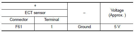
Is the inspection result normal? YES >> GO TO 3.
NO >> GO TO 2.
2.CHECK ENGINE COOLANT TEMPERATURE SENSOR POWER SUPPLY CIRCUIT
- Turn ignition switch OFF.
- Disconnect ECM harness connector.
- Check the continuity between ECT sensor harness connector and ECM harness connector.
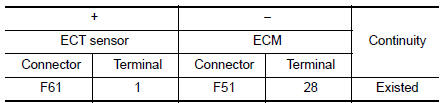
- Also check harness for short to ground.
Is the inspection result normal? YES >> Perform the trouble diagnosis for power supply circuit.
NO >> Repair or replace error-detected parts.
3.CHECK ENGINE COOLANT TEMPERATURE SENSOR GROUND CIRCUIT
- Turn ignition switch OFF.
- Disconnect ECM harness connector.
- Check the continuity between ECT sensor harness connector and ECM harness connector.
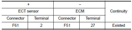
- Also check harness for short to ground to power.
Is the inspection result normal? YES >> GO TO 4.
NO >> Repair or replace error-detected parts.
4.CHECK ENGINE COOLANT TEMPERATURE SENSOR
Check the engine coolant temperature sensor. Refer to EC-212, "Component Inspection".
Is the inspection result normal? YES >> GO TO 5.
NO >> Replace engine coolant temperature sensor. Refer to CO-23, "Exploded View".
5.CHECK INTERMITTENT INCIDENT
Refer to GI-41, "Intermittent Incident".
>> INSPECTION END
Component Inspection
1.CHECK ENGINE COOLANT TEMPERATURE (ECT) SENSOR
- Turn ignition switch OFF.
- Disconnect ECT sensor harness connector.
- Remove ECT sensor.
- Check resistance between ect sensor terminals by heating with hot water as shown in the figure.
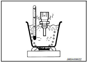
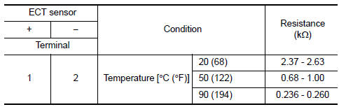
Is the inspection result normal?
YES >> INSPECTION END
NO >> Replace engine coolant temperature sensor. Refer to CO-23, "Exploded View".
 P0116 ECT sensor
DTC Description
DTC DETECTION LOGIC
DTC No.
CONSULT screen terms
(Trouble diagnosis content)
DTC detecting condition
P0116
ECT SENSOR
(Engine coolant temperature senso ...
 P0122, P0123 TP sensor
DTC Description
DTC DETECTION LOGIC
DTC No.
CONSULT screen terms
(Trouble diagnosis content)
DTC detecting condition
P0122
TP SEN 2/CIRC-B1
(Throttle/pedal position se ...
Other materials:
Removal and installation
HOOD
Exploded View
Hood hinge (RH)
Hood
Hood side seal
Hood front seal
Hood center seal
Bumper rubber
Hood insulator
Hood rod clamp
Hood support rod
Hood rod grommet
Hood hinge (LH)
HOOD ASSEMBLY
HOOD ASSEMBLY : Removal and Instal ...
Brake fluid
Drain and Refill
CAUTION:
Do not spill or splash brake fluid on painted surfaces. Brake
fluid may damage paint. If brake fluid is
splashed on painted areas, wash it away with water immediately.
Prior to repair, turn the ignition switch OFF, disconnect the
ABS actuator and ...
Back door window glass
Exploded View
Back door window glass
Clip
Clip
Removal and Installation
REMOVAL
Remove back door finisher. Refer to INT-38, "Removal and
Installation".
Remove back door lock. Refer to DLK-263, "DOOR LOCK : Removal and
Installation" (for i ...
