Nissan Rogue Service Manual: ABS actuator and electric unit (control unit)
Exploded View
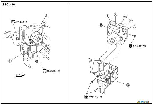
- ABS actuator and electric unit (control unit)
- Connector
- Bracket
- To front LH brake caliper
- To rear RH brake caliper
- From master cylinder secondary side
- From master cylinder primary side
- To rear LH brake caliper
- To front RH brake caliper
Removal and Installation
REMOVAL
CAUTION:
- To remove brake tube, use a flare nut wrench to prevent flare nuts and brake tube from being damaged.
- Do not remove actuator by holding harness.
NOTE: When removing components such as hoses, tubes/lines, etc., cap or plug openings to prevent fluid from spilling.
- Disconnect negative battery terminal. Refer to PG-75, "Exploded View".
- Remove the cowl top cover and cowl top extension. Refer to EXT-25, "Removal and Installation".
- Separate brake tubes from ABS actuator and electric unit (control unit). Refer to BR-22, "FRONT : Exploded View".
- Remove the brake booster vacuum hose. Refer to BR-32, "Removal and Installation".
- Separate the brake booster vacuum tube and place aside. Refer to BR-23, "FRONT : Removal and Installation".
- Disconnect the harness connector from the ABS actuator and electric unit (control unit).
- Remove ABS actuator and electric unit (control unit) bracket bolts and bushings.
- Remove ABS actuator and electric unit (control unit) from vehicle.
INSTALLATION
Installation is in the reverse order of removal.
- After work is completed, bleed air from brake tube. Refer to BR-16, "Bleeding Brake System".
- Adjust the neutral position of steering angle sensor. Refer to BRC-70, "Work Procedure".
- Perform calibration of the decel G sensor. Refer to BRC-72, "Work Procedure".
CAUTION:
- To install, use flare nut crowfoot and torque wrench.
- Do not reuse the bushings.
- Replace the ABS actuator if it has been dropped or sustained an impact.
- Do not install actuator by holding harness.
- After installing harness connector in the ABS actuator and electric unit (control unit), make sure connector is securely locked.
 Sensor rotor
FRONT SENSOR ROTOR
FRONT SENSOR ROTOR : Removal and Installation - Front Sensor Rotor
The front wheel sensor rotor is an integral part of the wheel hub and bearing
and cannot be disassembled.
R ...
 VDC off switch
Removal and Installation
REMOVAL
Remove the instrument lower panel LH. Refer to IP-14, "INSTRUMENT
PANEL ASSEMBLY : Removal
and Installation".
Release pawls using sui ...
Other materials:
Sensor power supply2 circuit
Description
ECM supplies a voltage of 5 V to some of the sensors systematically divided
into 2 groups, respectively.
Accordingly, when a short circuit develops in a sensor power source, a
malfunction may occur simultaneously
in the sensors belonging to the same group as the short-circuited ...
Precaution
Precaution for Supplemental Restraint System (SRS) "AIR BAG" and "SEAT
BELT
PRE-TENSIONER"
The Supplemental Restraint System such as “AIR BAG” and “SEAT BELT PRE-TENSIONER”,
used along
with a front seat belt, helps to reduce the risk or severity of injury to the
...
P0744 torque converter
DTC Description
DTC DETECTION LOGIC
DTC
CONSULT screen terms
(Trouble diagnosis content)
DTC detection condition
P0744
TORQUE CONVERTER
(Torque converter clutch circuit intermittent)
When all of the following conditions are satisfied and this state is
maintain ...
