Nissan Rogue Service Manual: Sensor power supply2 circuit
Description
ECM supplies a voltage of 5 V to some of the sensors systematically divided into 2 groups, respectively.
Accordingly, when a short circuit develops in a sensor power source, a malfunction may occur simultaneously in the sensors belonging to the same group as the short-circuited sensor.
Sensor power supply 1
- APP sensor 1
- CKP sensor (POS)
- Intake manifold runner control valve position sensor
- Refrigerant pressure sensor
- TP sensor
NOTE: If sensor power supply 1 circuit is malfunctioning, DTC P0643 is displayed.
Sensor power supply 2
- APP sensor 2
- CMP sensor (PHASE)
- EVT control position sensor
- EOP sensor
- MAF sensor
Diagnosis Procedure
1.CHECK APP SENSOR 2 POWER SUPPLY CIRCUIT-1
- Turn ignition switch OFF.
- Disconnect accelerator pedal position (APP) sensor harness connector.
- Turn ignition switch ON.
- Check the voltage between APP sensor harness connector and ground.
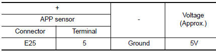
Is the inspection result normal? YES >> INSPECTION END
NO >> GO TO 2.
2.CHECK APP SENSOR 2 POWER SUPPLY CIRCUIT-2
- Turn ignition switch OFF.
- Disconnect ECM harness connector.
- Check the continuity between APP sensor harness connector and ECM harness connector.
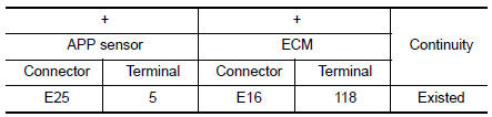
Is the inspection result normal? YES >> GO TO 3.
NO >> Repair open circuit.
3.CHECK SENSOR POWER SUPPLY 2 CIRCUIT
- Disconnect following sensors harness connector.
- Check harness for short to power and short to ground, between the following terminals.
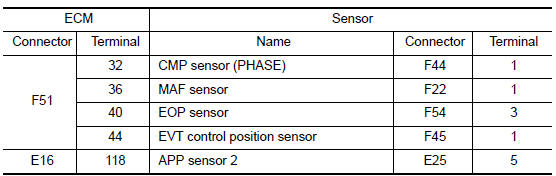
Is the inspection result normal? YES >> GO TO 4.
NO >> Repair short to ground or short to power in harness or connectors.
4.CHECK COMPONENTS
Check the following.
- APP sensor 2 (Refer to EC-444, "Component Inspection".)
- Camshaft position sensor (PHASE) (Refer to EC-300, "Component Inspection (Camshaft position sensor)".)
- EVT control position sensor (Refer to EC-387, "Component Inspection".)
- EOP sensor (Refer toEC-360, "Component Inspection".)
- MAF sensor (Refer to EC-200, "Component Inspection".)
Is the inspection result normal? YES >> Refer to GI-41, "Intermittent Incident".
NO >> Replace malfunctioning component.
 Refrigerant pressure sensor
Component Function Check
1.CHECK REFRIGERANT PRESSURE SENSOR FUNCTION
Start engine and warm it up to normal operating temperature.
Turn A/C switch and blower fan switch ON.
...

Other materials:
Precaution
Precaution for Supplemental Restraint System (SRS) "AIR BAG" and "SEAT
BELT
PRE-TENSIONER"
The Supplemental Restraint System such as “AIR BAG” and “SEAT BELT
PRE-TENSIONER”, used along
with a front seat belt, helps to reduce the risk or severity of injury to the
...
Luggage hooks
When securing items using luggage hooks located
on the back of the seat or side finisher do
not apply a load over more than 6.5 lbs (29 N) to
a single hook.
The luggage hooks that are located on the floor
should have loads less than 110 lbs (490 N) to a
single hook.
The luggage hooks ...
System description
COMPONENT PARTS
Component Parts Location
View with back door finisher removed
View with glove box assembly removed
View with front bumper removed
View with front bumper removed
Rear under body LH
View with luggage rear plate removed
No.
Component ...
