Nissan Rogue (T33) 2021-Present Service Manual: With Idle Start/stop :: System Description
Component Parts
Component Parts Location
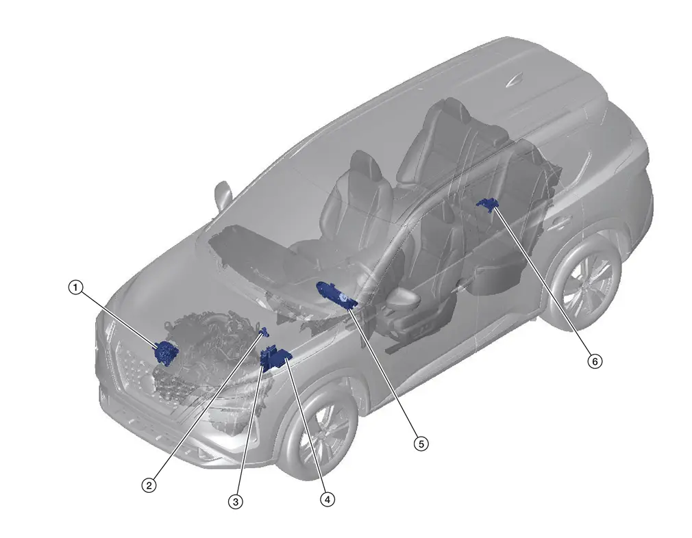
| No. | Component | Function |
|---|---|---|
| 1. | Sub starter & generator | Refer to Sub starter & generator. |
| 2. | Battery current sensor (with battery temperature sensor) | Refer to 12V Battery Current Sensor . |
| 3. | ECM (Engine Control Module | The ECM transmits the generator voltage request signal received from the IPDM E/R to the generator via LIN communication signal. Refer to Component Parts Location for detailed copmonent location. |
| 4. | IPDM E/R (Intelligent Power Distribution Module Engine Room) | The IPDM E/R sends the generator voltage request signal to the ECM via CAN communication. Refer to Component Parts Location for detailed component location. |
| 5. | Combination meter | The control module inside generator warning function activates to
illuminate the charge warning lamp if any of the following symptoms
occur while generator is operating:
|
| 6. | Power network separate relay (If so equipped) | Electric network separator cuts off the circuit between DC/DC converter side and 12 v sub-battery (Li-ion battery) side according to voltage fluctuation. Refer to POWER NETWORK SEPARATE RELAY. |
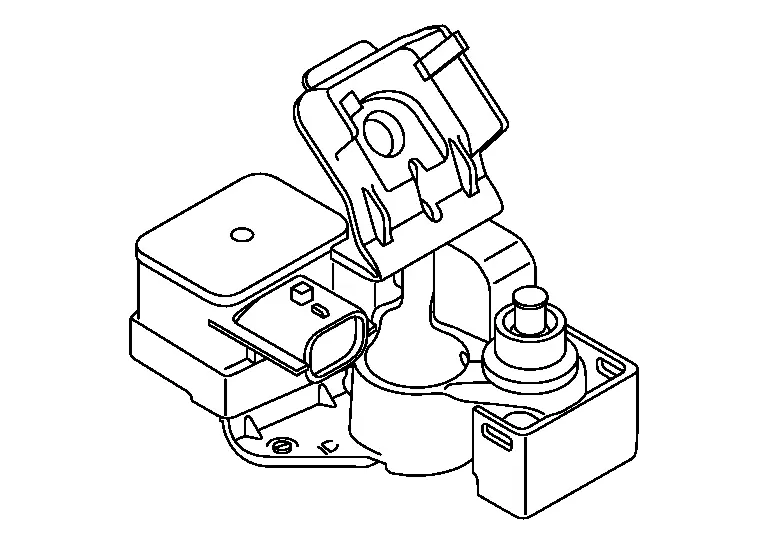
Sub starter & generator
-
Sub starter & generator is installed to LH side of engine.
-
Sub starter & generator has integrated control unit, and transmits/receives signal via ECM and CAN communication.
-
Sub starter & generator controls power generation voltage by target power generation voltage based on recived power generation voltage request signal.
-
During normal driving, it performs generation control according to the power generation command signal from the ECM.
-
It also has self-diagnosis function.
-
ECM transmits target charging voltage value to sub starter & generator via CAN communication.
-
When sub starter & generator received the signal, it controls power generation voltage by incorporated control unit.
-
When the ECM determines that the Nissan Ariya vehicle is decelerating, it increases the amount of power generated by the sub starter & generator based on the reference values of each sensor, and recovers the power to the 12V battery.
-
For restart control, refer to System Description.
12V Battery Current Sensor
-
Battery current sensor is installed to 12V battery negative cable.
-
Battery current sensor transmits battery current sensor signal via LIN communication to IPDM E/R. Battery current sensor measure charging/discharging current of 12V battery and temperature around 12V battery, and sends its signal to IPDM E/R. IPDM E/R controls power generation by sending power generation command value signal based on following signals to ECM. As a result, engine load can be reduced.
-
Battery current sensor measures charging/discharging current of 12V battery and sends its signal to IPDM E/R.
-
Battery temperature sensor is integrated in battery current sensor. Battery temperature sensor measures temperature around 12V battery.
-
Battery current sensor measures charging/discharging current of 12V battery and sends its signal to IPDM E/R.
-
Battery temperature sensor measures temperature around 12V battery using IC temperature sensor.
System
Energy Management System
System Description
SYSTEM DIAGRAM
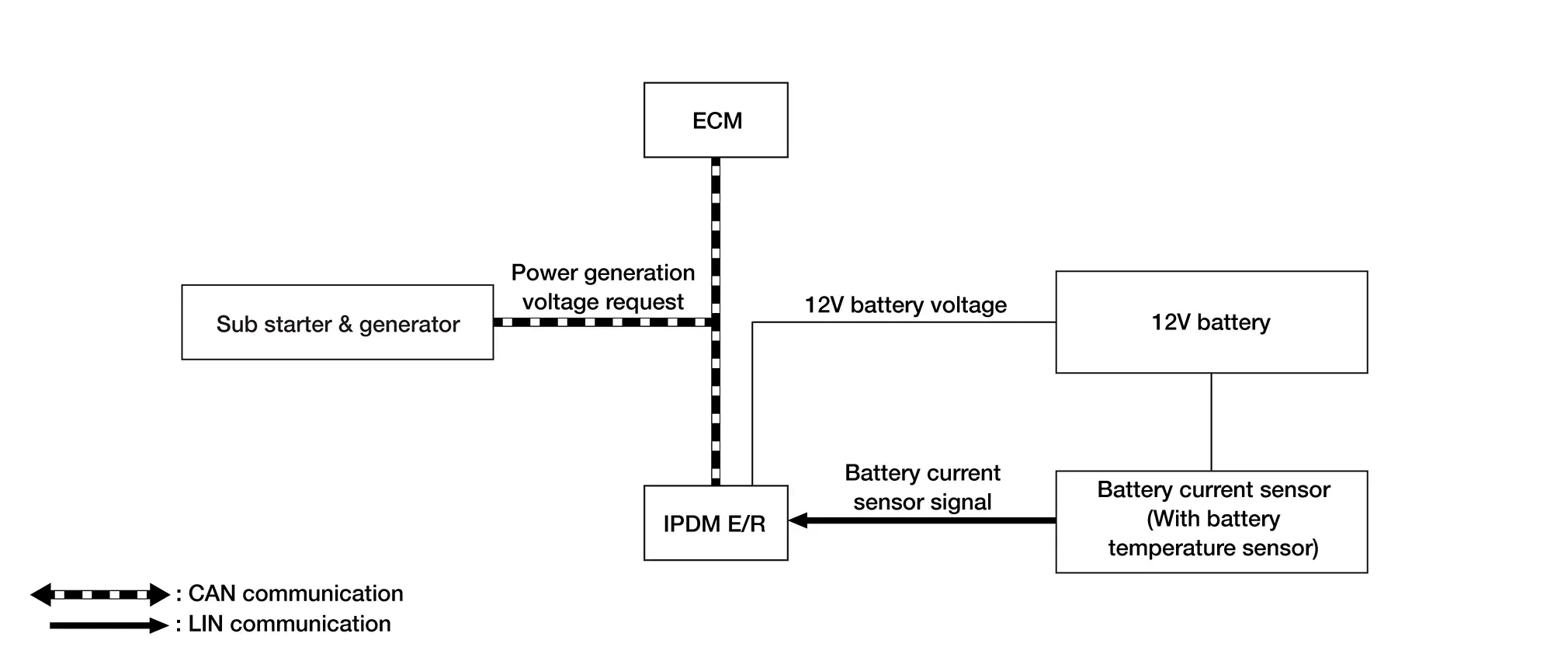
| Component | Function |
|---|---|
| Sub starter & generator | Refer to Sub starter & generator. |
| IPDM E/R | IPDM E/R monitors charge and discharge state of each battery. Calculate the power generation voltage request value according to the battery status and transmits to the ECM as a power generation voltage request signal. |
| ECM | ECM transmits the received power generation voltage request signal to sub starter & generator via CAN communication. |
| Battery current sensor | Refer to 12V Battery Current Sensor. |
POWER GENERATION CONTROL
-
Battery current sensor (incorporated temperature sensor) transmits the 12V battery status to IPDM E/R via LIN communication.
-
IPDM E/R calculate the target power generation voltage according to battery status and transmits the power generation voltage request signal to ECM via CAN communication.
-
ECM transmits the alternator voltage request value signal to the sub starter & generator via CAN communication.
-
The sub starter & generator controls the generated voltage with the target power generation voltage based on the received alternator voltage request value signal.
-
When there is no power generation command signal, the sub starter & generator performs normal generation according to the control unit characteristics.
 NOTE:
NOTE:
-
When something goes wrong with the variable power generation voltage control system, it will perform normal generation according to the control unit characteristics.
-
ECM determines Nissan Ariya vehicle condition and performs regenerative control.
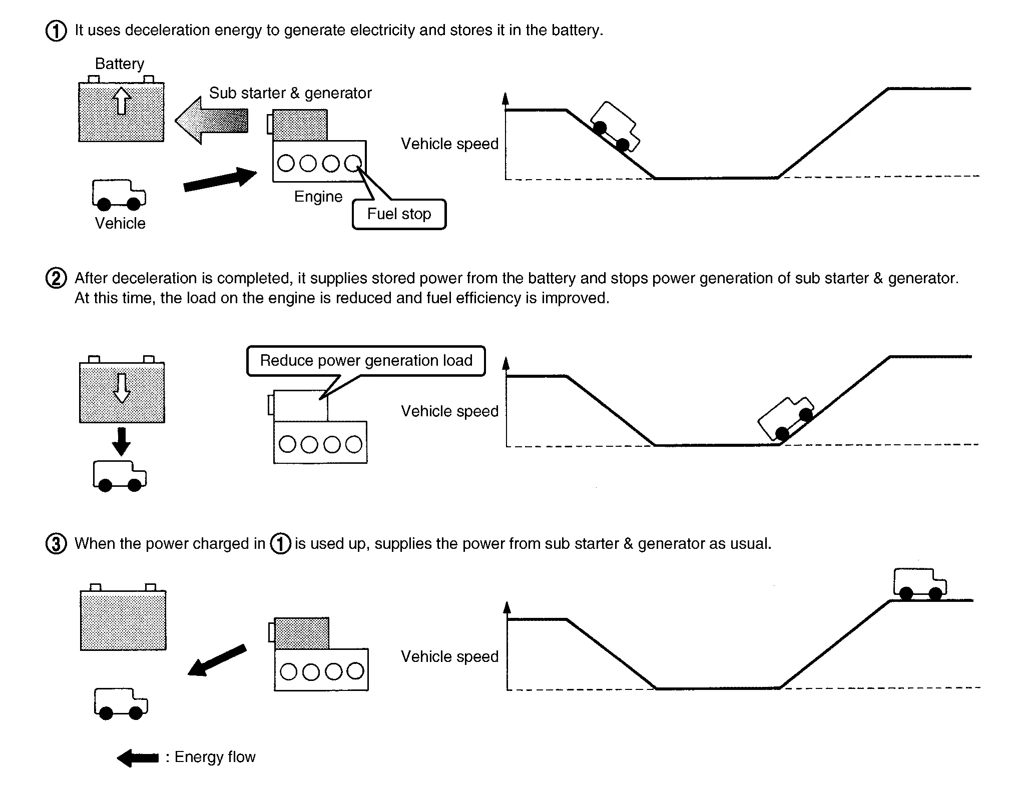
REGENERATIVE CONTROL
-
When the ECM determines that the vehicle is decelerating, it increases the amount of power generated by the sub starter & generator based on the reference values of each sensor, and recovers the power to the 12V battery.
-
After deceleration is completed, it supplies stored power and stops power generation of sub starter & generator. At this time, the load on the engine is reduced and fuel efficiency is improved.
Information Display (combination Meter)
12V battery charge warning
DESIGN/PURPOSE
12V battery charge warning warns in following case with 12V battery charge warning lamp displaying.
NOTE:
For function of 12V battery charge warning lamp, refer to 12V Battery Charge Warning Lamp.
| Symbol | Message |
|---|---|
|
|
- |
SYNCHRONIZATION WITH MASTER WARNING LAMP
Synchronization is applied.
For master warning lamp, refer to Master Warning Lamp.
SYSTEM DIAGRAM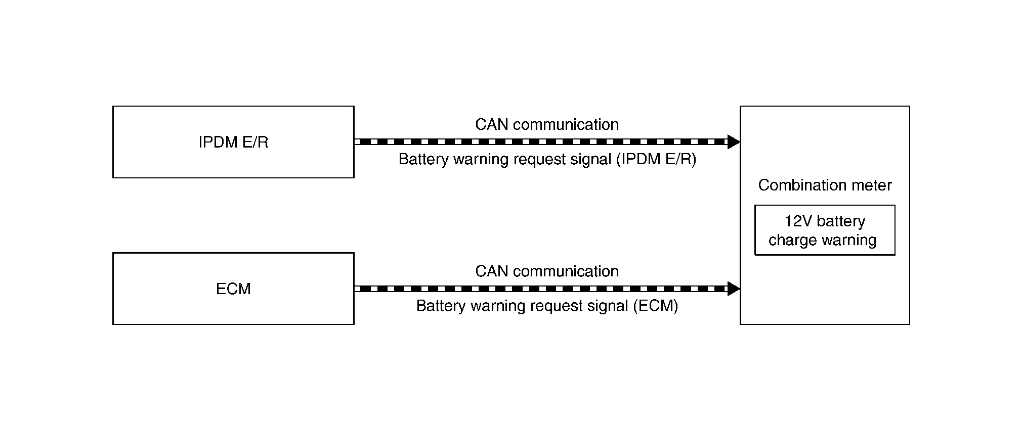
SYSTEM DIAGRAM
SIGNAL PATH
-
ECM transmits battery warning request signal (ECM) to combination meter via CAN communication when overvoltage or low voltage is detected on battery positive terminal or sub starter & generator malfunction.
-
IPDM E/R transmits battery warning request signal (IPDM E/R) to combination meter via CAN communication when overvoltage or low voltage is detected on battery positive terminal.
-
Combination meter indicates 12V battery charge warning judged with battery warning request signal received from ECM or IPDM E/R.
WARNING/INDICATOR OPERATING CONDITION
When any of the following symptoms occur while sub starter & generator is operating:
-
Communication between sub starter & generator and ECM is malfunction detected.
-
Communication between combination meter and ECM is malfunction detected.
-
Communication between combination meter and IPDM E/R is malfunction detected.
-
Sub starter & generator detected internal malfunction.
-
Overvoltage detected on battery positive terminal.
-
Low voltage detected on battery positive terminal.
-
When the engine stall is detected while stop/ start before Nissan Ariya vehicle halt is prohibited.
WARNING INDICATOR CANCEL CONDITION
Ignition switch is OFF.
TIMING CHART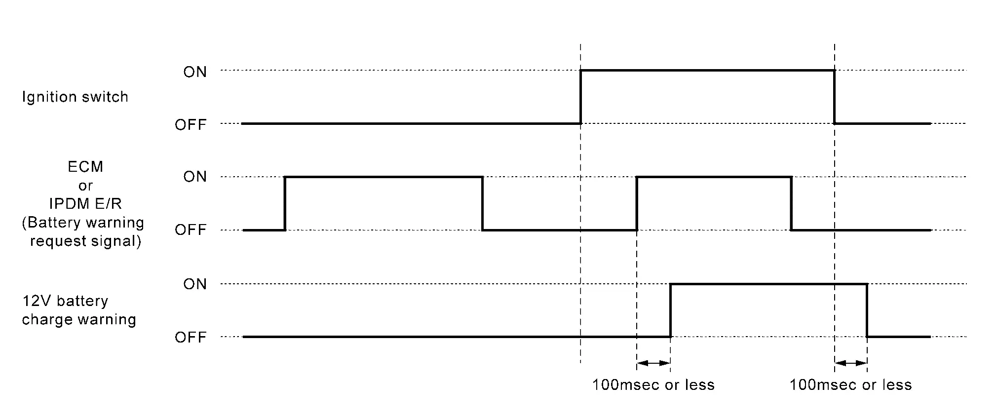
Warning/indicator/chime List
Warning Lamps/Indicator Lamps
| Item | Design | Reference |
|---|---|---|
| Charge warning lamp |  |
For layout, refer to Design (Type A) or Design (Type B). |
| For function, refer to 12V Battery Charge Warning Lamp (7 INCH INFORMATION DISPLAY) or 12V Battery Charge Warning Lamp (FULL TFT METER). |
Diagnosis System (sub Starter & Generator)
CONSULT Function (SUB STARTER & GENERATOR)
APPLICATION ITEM
CONSULT performs the following functions via CAN communication with sub starter & generator.
| Diagnosis Mode | CGW Status | Description | ||
|---|---|---|---|---|
| Restriced Mode | Diag Test Mode | Open Mode | ||
| Self Diagnostic Result | Display | Display | Display | Display non-network DTC which Sub starter & generator memorizes. |
| ECU Identification | Display | Display | Display | Allows confirmation of Sub starter & generator part number. |
SELF DIAGNOSTIC RESULT
Refer to
Freeze Frame Data (FFD)
The sub starter & generator records the vehicle condition at the time a particular DTC is detected, and displays on CONSULT.
| Monitor Item [Unit] | Description |
|---|---|
| ODO/TRIP METER [km] | Displays the total mileage (Odometer value) of the moment a DTC is detected. |
CGW INFORMATION
Display the diagnosis mode which a user can perform in Diag Test mode/Open Mode by switching the CGW status from Restricted mode to Diag Test Mode/Open Mode.
For the method of switching CAN Gateway status. Refer to CONSULT Function.
Other materials:
Service Data and Specifications (sds)
Road Wheel
ALUMINUM WHEEL Item Limit
Runout
Axial runout
Less than 0.3 mm (0.012 in)
Radial runout
Allowable unbalance
Dynamic (At flange)
Less than 5 g (0.17 oz) (one side)
Static (At flange)
Less than 10 g (0.35 oz)
STEEL WHEEL (EMERGENCY) Item Limit
Runo ...
Basic information
The following are approximate capacities for your Nissan Rogue.
Actual refill capacities may vary slightly. When refilling, always follow the procedure described in the "8. Do-it-yourself" section to confirm the proper amount for your Nissan Rogue.
Fuel
Engine oil
Drain and refill
Genuine "NI ...
P0036 Ho2s2 Heater
DTC Description
DTC DETECTION LOGIC DTC
CONSULT screen terms
(Trouble diagnosis content)
DTC detection condition
P0036
00
HO2S1 HTR (B1)
(HO2S Heater Control Circuit Bank 1 Sensor 2)
Diagnosis condition
―
Signal (terminal)
...