Nissan Rogue Service Manual: VDC off switch
Component Function Check
1.CHECK VDC OFF SWITCH OPERATION
Check that VDC OFF indicator lamp in combination meter turns ON/OFF when VDC OFF switch is operated.
Is the inspection result normal? YES >> INSPECTION END
NO >> Proceed to BRC-117, "Diagnosis Procedure".
Diagnosis Procedure
1.CHECK VDC OFF SWITCH CIRCUIT
- Turn the ignition switch OFF.
- Disconnect ABS actuator and electric unit (control unit) harness connector.
- Disconnect VDC OFF switch harness connector.
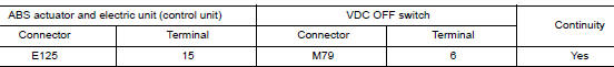
- Check the continuity between ABS actuator and electric unit (control unit) harness connector and VDC OFF switch harness connector.
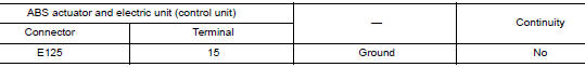
- Check the continuity between ABS actuator and electric unit (control unit) harness connector and ground.
Is the inspection result normal? YES >> GO TO 2.
NO >> Repair or replace error-detected parts.
2.CHECK VDC OFF SWITCH GROUND CIRCUIT
Check the continuity between VDC OFF switch harness connector and ground.

the inspection result normal? YES >> GO TO 3.
NO >> Repair or replace error-detected parts.
3.CHECK VDC OFF SWITCH
Check the VDC OFF switch. Refer to BRC-118, "Component Inspection".
Is the inspection result normal? YES >> GO TO 4.
NO >> Replace the VDC OFF switch. Refer to BRC-138, "Removal and Installation".
4.CHECK VDC OFF SWITCH SIGNAL
 With CONSULT
- Connect ABS actuator and electric unit (control unit) harness connector.
- Connect VDC OFF switch harness connector.
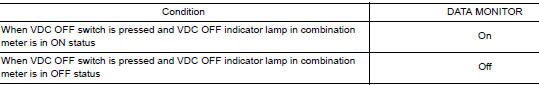
- Select “ABS”, “DATA MONITOR” and “OFF SW” according to this order. Check the VDC OFF switch signal.
Is the inspection result normal? YES >> Inspection End.
NO >> GO TO 5.
5.CHECK TERMINAL
- Check the ABS actuator and electric unit (control unit) pin terminals for damage or loose connection with harness connector.
- Check the VDC OFF switch pin terminals for damage or loose connection with harness connector.
Is the inspection result normal? YES >> Replace the ABS actuator and electric unit (control unit). Refer to BRC-136, "Removal and Installation".
NO >> Repair or replace error-detected parts.
Component Inspection
1.CHECK VDC OFF SWITCH
- Turn the ignition switch OFF.
- Disconnect VDC OFF switch harness connector.
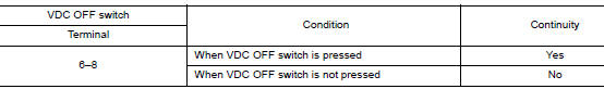
- Check the continuity between terminals of VDC OFF switch connector.
Is the inspection result normal? YES >> Inspection End.
NO >> Replace the VDC OFF switch. Refer to BRC-138, "Removal and Installation".
 Parking brake switch
Component Function Check
1.CHECK PARKING BRAKE SWITCH OPERATION
Check that brake warning lamp in combination meter turns ON/OFF when parking
brake is operated.
Is the inspection result normal?
...
 ABC warning lamp
Component Function Check
1.CHECK ABS WARNING LAMP FUNCTION
Check that ABS warning lamp in combination meter turns ON for 1 second after
ignition switch is turned ON.
CAUTION:
Never start the eng ...
Other materials:
Charging system preliminary inspection
Diagnosis Procedure
1.CHECK BATTERY TERMINALS CONNECTION
Check if battery terminals are clean and tight.
Is the inspection result normal?
YES >> GO TO 2.
NO >> Repair battery terminal connection. Confirm repair by performing complete
Charging system test
using EXP-800 NI or G ...
Easy fill tire alert does not activate
Description
The easy fill tire alert does not function while inflating a tire when the
select lever position is in P-range with the
power switch ON or with the vehicle set to READY.
NOTE:
After starting to inflate the tire, it takes a few seconds for
the easy fill tire alert to fun ...
U1000 CAN COMM circuit
Description
CAN (Controller Area Network) is a serial communication line for real-time
application. It is an on-vehicle multiplex
communication line with high data communication speed and excellent malfunction
detection ability.
Many electronic control units are equipped onto a vehicle, and ...
