Nissan Rogue Service Manual: Parking brake switch
Component Function Check
1.CHECK PARKING BRAKE SWITCH OPERATION
Check that brake warning lamp in combination meter turns ON/OFF when parking brake is operated.
Is the inspection result normal? YES >> Inspection End.
NO >> Proceed to BRC-115, "Diagnosis Procedure".
Diagnosis Procedure
1.CHECK PARKING BRAKE SWITCH CIRCUIT
- Turn the ignition switch OFF.
- Disconnect parking brake switch harness connector.
- Disconnect combination meter harness connector.
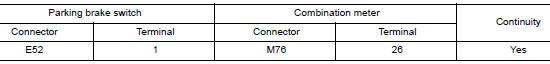
- Check the continuity between parking brake switch harness connector and combination meter harness connector.
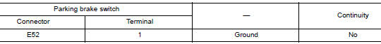
- Check the continuity between parking brake switch harness connector and ground.
Is the inspection result normal? YES >> GO TO 2.
NO >> Repair or replace error-detected parts.
2.CHECK PARKING BRAKE SWITCH
Check the parking brake switch. Refer to PB-4, "Inspection and Adjustment".
Is the inspection result normal? YES >> GO TO 3.
NO >> Replace the parking brake switch. Refer to PB-7, "Exploded View".
3.CHECK PARKING BRAKE SWITCH SIGNAL
 With CONSULT
- Connect parking brake switch harness connector.
- Connect combination meter harness connector.
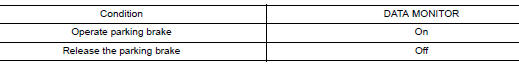
- Select “ABS”, “DATA MONITOR” and “PARK BRAKE SW” according to this order. Check the parking brake switch signal.
Is the inspection result normal? YES >> Inspection End.
NO >> GO TO 4.
4.CHECK COMBINATION METER
Check the combination meter. Refer to MWI-21, "CONSULT Function (METER/M&A)".
Is the inspection result normal? YES >> GO TO 5.
NO >> Repair or replace combination meter. Refer to MWI-82, "Removal and Installation".
5.CHECK TERMINAL
- Check the combination meter pin terminals for damage or loose connection with harness connector.
- Check the parking brake switch pin terminals for damage or loose connection with harness connector.
Is the inspection result normal? YES >> Replace the ABS actuator and electric unit (control unit). Refer to BRC-136, "Removal and Installation".
NO >> Repair or replace error-detected parts.
Component Inspection
1.CHECK PARKING BRAKE SWITCH
- Turn the ignition switch OFF.
- Disconnect parking brake switch harness connector.
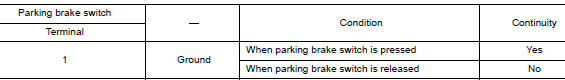
- Check the continuity between parking brake switch terminal and ground.
Is the inspection result normal? YES >> Inspection End.
NO >> Replace the parking brake switch. Refer to PB-7, "Exploded View".
 Power supply and ground circuit
Diagnosis Procedure
Regarding Wiring Diagram information, refer to PCS-24, "Wiring Diagram".
1. CHECK FUSE AND FUSIBLE LINKS
Check that the following IPDM E/R fuse or fusible links are no ...
 VDC off switch
Component Function Check
1.CHECK VDC OFF SWITCH OPERATION
Check that VDC OFF indicator lamp in combination meter turns ON/OFF when VDC
OFF switch is operated.
Is the inspection result normal?
...
Other materials:
Cylinder block
Exploded View
Cylinder block
Top ring
Second ring
Oil ring
Snap ring
Piston
Connecting rod
Piston pin
Connecting rod bearing
Rear oil seal
Reinforcement plate
Drive plate
Signal plate
Pilot convert ...
ECU diagnosis information
EPS CONTROL UNIT
Reference Value
VALUES ON THE DIAGNOSIS TOOL
CAUTION:
The output signal indicates the EPS control unit calculation data. The normal
values will be displayed
even in the event that the output circuit (harness) is open.
NOTE:
The following table includes information (items) ...
Component parts
Component Parts Location
Condenser
Compressor
Refrigerant pressure sensor
Liquid tank
Expansion valve
Evaporator
Component Description
Component
Description
Compressor
Intakes, compresses and discharges refrigerant to circulate
refrigerant ...
