Nissan Rogue Service Manual: Power supply and ground circuit
Diagnosis Procedure
Regarding Wiring Diagram information, refer to PCS-24, "Wiring Diagram".
1. CHECK FUSE AND FUSIBLE LINKS
Check that the following IPDM E/R fuse or fusible links are not blown.
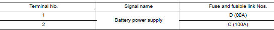
Is the fuse blown? YES >> Replace the blown fuse or fusible link after repairing the affected circuit.
NO >> GO TO 2.
2. CHECK BATTERY POWER SUPPLY CIRCUIT
- Disconnect IPDM E/R connector E118.
- Check voltage between IPDM E/R connector E118 and ground.
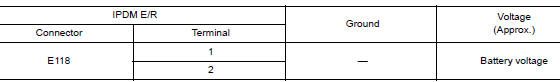
Is the inspection result normal? YES >> GO TO 3.
NO >> Repair or replace harness or connectors.
3. CHECK GROUND CIRCUIT
- Disconnect IPDM E/R connectors E119, E120 and E121.
- Check continuity between IPDM E/R connectors and ground.
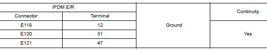
Is the inspection result normal? YES >> Inspection End.
NO >> Repair or replace harness or connectors.
 U1000 CAN COMM CIRCUIT
Description
CAN communication allows a high rate of information transmission through the
two communication lines
(CAN-H line and CAN-L line) connecting various control units in the system. Each
...
 Parking brake switch
Component Function Check
1.CHECK PARKING BRAKE SWITCH OPERATION
Check that brake warning lamp in combination meter turns ON/OFF when parking
brake is operated.
Is the inspection result normal?
...
Other materials:
CD care and cleaning
Handle a CD by its edges. Do not bend the
disc. Never touch the surface of the disc.
Always place the discs in the storage case
when they are not being used.
To clean a disc, wipe the surface from the
center to the outer edge using a clean, soft
cloth. Do not wipe the ...
Door mirror
Exploded View
Door mirror
Door mirror corner finisher
Door mirror rear finisher
Side turn signal lamp
Side camera (if equipped)
Door mirror glass
Pawl
Removal and Installation
REMOVAL
Remove front door finisher. Refer to INT-15, "Removal and
...
Luggage room lamp
Removal and Installation
REMOVAL
Insert a suitable tool (A) into the gap between the luggage lower
finisher (RH) (2) and the top of luggage room lamp (1) to release
the pawl.
: Pawl
Disconnect the harness connector from the luggage room lamp and remove.
INSTALLATION
Installati ...
