Nissan Rogue Service Manual: ECU diagnosis information
EPS CONTROL UNIT
Reference Value
VALUES ON THE DIAGNOSIS TOOL
CAUTION: The output signal indicates the EPS control unit calculation data. The normal values will be displayed even in the event that the output circuit (harness) is open.
NOTE: The following table includes information (items) inapplicable to this vehicle. For information (items) applicable to this vehicle, refer to CONSULT display items.
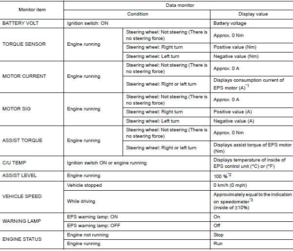
*1: Almost in accordance with the value of “MOTOR SIG”. It is not a
malfunction though these values are not
accorded when steering quickly.
*2: Normally displays 100%. In case of an excessive stationary steering, the
assist curvature gradually falls.
However, it returns to 100% when left standing.
*3: It is not a malfunction, though it might not be corresponding just after
ignition switch in turned ON
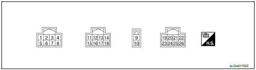
TERMINAL LAYOUT
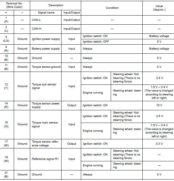
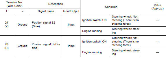
PHYSICAL VALUES
Fail-Safe
- If any malfunction occurs in the system and the control unit detects the malfunction, the EPS warning lamp in the combination meter turns ON to indicate system malfunction.
- When EPS warning lamp is ON, the system enters into a manual steering state. (turning force at steering wheel becomes heavy.)
- Under abnormal vehicle speed signal conditions, vehicle speed is judged as constant.
Protection Function
EPS control unit decreases the output signal to EPS motor during continuous extreme use of the power steering function (e.g., full steering) for protection of the EPS motor and EPS control unit (Overload protection control).
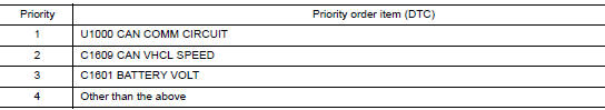
DTC Inspection Priority Chart
When multiple DTCs are detected simultaneously, check one by one depending on the following priority list.
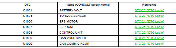
DTC Index
 Diagnosis system (EPS control unit)
CONSULT Function
FUNCTION
CONSULT can display each diagnostic item using the diagnostic test modes
shown following
Diagnostic test mode
Function
ECU identification
The p ...
 Wiring diagram
EPS SYSTEM
Wiring Diagram
...
Other materials:
Using the system
The NISSAN Voice Recognition system allows
hands-free operation of the Bluetooth® Hands-
Free Phone System.
If the vehicle is in motion, some commands may
not be available so full attention may be given to
vehicle operation.
Initialization
When the ignition switch is placed in the ON
posi ...
Interior room lamp control circuit
Description
Controls each interior room lamp (ground side) by PWM signal.
NOTE:
PWM signal control period is approximately 250 Hz (in the gradual
brightening/dimming).
Component Function Check
CAUTION:
Before performing the diagnosis, check that the following is normal.
Interior ro ...
Rear window defogger and door mirror defogger do not operate
Diagnosis Procedure
Regarding Wiring Diagram information, refer to DEF-12, "Wiring Diagram".
1. CHECK REAR WINDOW DEFOGGER SWITCH
Check rear window defogger switch.
Refer to DEF-22, "WITH MANUAL A/C : Component Function Check".
Is the inspection result normal?
YES >& ...
