Nissan Rogue Service Manual: Charging system preliminary inspection
Diagnosis Procedure
1.CHECK BATTERY TERMINALS CONNECTION
Check if battery terminals are clean and tight.
Is the inspection result normal? YES >> GO TO 2.
NO >> Repair battery terminal connection. Confirm repair by performing complete Charging system test using EXP-800 NI or GR8-1200 NI (if available). Refer to the applicable Instruction Manual for proper testing procedures.
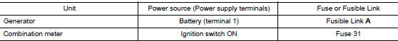
2.CHECK FUSE
Check for blown fuse and fusible link.
Is the inspection result normal? YES >> GO TO 3.
NO >> Replace the blown fuse or fusible link after repairing the affected circuit.
3.CHECK DRIVE BELT TENSION
Check drive belt tension. Refer to MA-13, "DRIVE BELTS : Tension Adjustment".
Is the inspection result normal? YES >> Inspection End.
NO >> Repair as needed.

 Power generation voltage variable control system operation
inspection
Power generation voltage variable control system operation
inspection
Diagnosis Procedure
Regarding Wiring Diagram information. Refer to CHG-7, "Wiring Diagram".
CAUTION:
When performing this inspection, always use a charged battery that has completed
the ...
Other materials:
Preparation
Special Service Tool
The actual shape of the tool may differ from those illustrated here.
Tool number
(TechMate No.)
Tool name
Description
KV991J0080
(J-45741)
ABS active wheel sensor tester
Checking operation of ABS active wheel sensors
Comm ...
How to erase permanent DTC
Description
OUTLINE
When a DTC is stored in ECM
When a DTC is stored in ECM and MIL is ON, a permanent DTC is erased with MIL
shutoff if the same malfunction
is not detected after performing the driving pattern for MIL shutoff three times
in a raw.
*1: When the same malfunction is detecte ...
Interior room lamp power supply circuit
Description
Provides the interior room lamp power supply. Also cuts the power supply when
the interior room lamp battery
saver is activating.
Component Function Check
1.CHECK INTERIOR ROOM LAMP POWER SUPPLY FUNCTION
CONSULT ACTIVE TEST
Turn power switch ON.
Turn each interio ...
