Nissan Rogue Service Manual: Power generation voltage variable control system operation inspection
Diagnosis Procedure
Regarding Wiring Diagram information. Refer to CHG-7, "Wiring Diagram".
CAUTION: When performing this inspection, always use a charged battery that has completed the battery inspection.
(When the charging rate of the battery is low, the response speed of the voltage change will become slow. This can cause an incorrect inspection.)
1.CHECK ECM (CONSULT)
Perform ECM self-diagnosis with CONSULT. Refer to EC-67, "CONSULT Function".
Self-diagnostic results content No malfunction detected>> GO TO 2.
Malfunction detected>> Check applicable parts, and repair or replace corresponding parts.
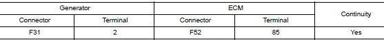
2.CHECK HARNESS BETWEEN GENERATOR AND ECM
- Turn ignition switch OFF.
- Disconnect generator connector and ECM connector.
- Check continuity between generator harness connector and ECM harness connector.
- Check continuity between generator harness connector and ground.
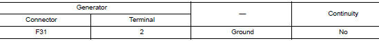
Is the inspection result normal? YES >> Replace ECM. Refer to EC-499, "Removal and Installation".
NO >> Repair harness or connectors between ECM and generator.
 Charging system preliminary inspection
Diagnosis Procedure
1.CHECK BATTERY TERMINALS CONNECTION
Check if battery terminals are clean and tight.
Is the inspection result normal?
YES >> GO TO 2.
NO >> Repair battery term ...
 B terminal circuit
Description
“B” terminal circuit supplies power to charge the battery and to operate the
vehicles electrical system.
Diagnosis Procedure
Regarding Wiring Diagram information. Refer to CHG-7, ...
Other materials:
Inside mirror
Exploded View
MANUAL ANTI-DAZZLING
Windshield glass
Mirror base
Inside mirror
AUTO ANTI-DAZZLING
Windshield glass
Mirror base
Inside mirror
Inside mirror finisher
Harness connector
Bolt
Removal and Installation
MANUAL ANTI-DAZZLING
Removal ...
Precaution
Precaution for Supplemental Restraint System (SRS) "AIR BAG" and "SEAT
BELT
PRE-TENSIONER"
The Supplemental Restraint System such as “AIR BAG” and “SEAT BELT PRE-TENSIONER”,
used along
with a front seat belt, helps to reduce the risk or severity of injury to the
...
Unbalance steering wheel turning force and return between
right and left
Description
Unbalance steering wheel turning force and return between right and left.
Diagnosis Procedure
1.CHECK THE ILLUMINATION OF THE EPS WARNING LAMP
Check the EPS warning lamp while engine is running.
Does the EPS warning lamp turn OFF?
YES >> GO TO 2.
NO >> Refer to STC ...
