Nissan Rogue Service Manual: B terminal circuit
Description
“B” terminal circuit supplies power to charge the battery and to operate the vehicles electrical system.
Diagnosis Procedure
Regarding Wiring Diagram information. Refer to CHG-7, "Wiring Diagram".
1.CHECK “B” TERMINAL CONNECTION
- Turn ignition switch OFF.
- Check if “B” terminal is clean and tight.
Is the inspection result normal? YES >> GO TO 2.
NO >> Repair terminal “B” connection. Confirm repair by performing complete Charging system test using the EXP-800 NI or GR8-1200 NI (if available). Refer to applicable Instruction Manual for proper testing procedures.
2.CHECK “B” TERMINAL CIRCUIT
Check voltage between generator “B” terminal and ground.
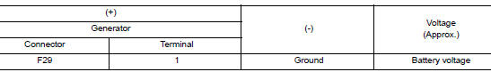
Is the inspection result normal? YES >> GO TO 3.
NO >> Check harness for open between generator and fusible link.
3.CHECK “B” TERMINAL CONNECTION (VOLTAGE DROP TEST)
- Start engine, then engine running at idle and warm.
- Check voltage between battery positive terminal and generator connector “B” terminal.
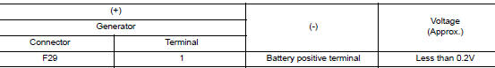
Is the inspection result normal? YES >> “B” terminal circuit is normal. Refer to CHG-11, "Work Flow (With EXP-800 NI or GR8-1200 NI)" or CHG-14, "Work Flow (Without EXP-800 NI or GR8-1200 NI)".
NO >> Check harness between battery and generator for continuity.
 Power generation voltage variable control system operation
inspection
Power generation voltage variable control system operation
inspection
Diagnosis Procedure
Regarding Wiring Diagram information. Refer to CHG-7, "Wiring Diagram".
CAUTION:
When performing this inspection, always use a charged battery that has completed
the ...
 Symptom diagnosis
CHARGING SYSTEM
Symptom Table
...
Other materials:
Ground
Ground Distribution
MAIN HARNESS
ENGINE ROOM HARNESS
ENGINE CONTROL HARNESS
BODY HARNESS
BODY NO. 2 HARNESS
...
Battery terminal with fusible link
Exploded View
Cover
Fusible link box (battery)
Positive cable
Battery
Harness connector
Front
Removal and Installation
REMOVAL
Loosen battery terminal nuts and disconnect both negative and
positive terminals from the battery.
CAUTION:
To prevent ...
System
System Description
SYSTEM DIAGRAM
POWER WINDOW OPERATION
Main power window and door lock/unlock switch can open/close all
windows.
Front and rear power window switches can open/close the
corresponding windows.
POWER WINDOW AUTO-OPERATION (FRONT DRIVER SIDE)
AUTO UP/DOW ...
