Nissan Rogue Service Manual: U1044 ENG comm circuit
DTC Description
DTC DETECTION LOGIC
| DTC No. | CONSULT screen terms (Trouble diagnosis content) | DTC detecting condition |
| U1044 | ENG COMM CIRCUIT (Engine communication circuit | A signal voltage of LIN communication between ECM and generator is excessively low or excessively high |
POSSIBLE CAUSE
- Harness or connectors (LIN communication circuit is open or shorted.)
- Generator
FAIL-SAFE
Not applicable
DTC CONFIRMATION PROCEDURE
1.PRECONDITIONING
If DTC Confirmation Procedure has been previously conducted. always perform the following procedure before conducting the next test.
- Turn ignition switch OFF and wait at least 10 seconds.
- Turn ignition switch ON.
- Turn ignition switch OFF and wait at least 10 seconds.
>> GO TO 2.
2.PERFORM DTC CONFIRMATION PROCEDURE
- Turn ignition ON and wait at least 10 seconds.
- Check DTC.
Is DTC detected? YES >> Proceed to EC-173, "Diagnosis Procedure".
NO >> INSPECTION END
Diagnosis Procedure
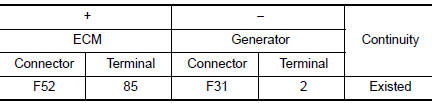
1.CHECK LIN COMMUNICATION CIRCUIT
- Turn ignition switch OFF.
- Disconnect ECM harness connector and generator harness connector.
- Check the continuity between ECM harness connector and generator harness connector.
- Also check harness for short to power and short to ground.
Is the inspection result normal? YES >> GO TO 2.
NO >> Repair or replace error-detected parts.
2.REPLACE GENERATOR
- Replace generator. Refer to CHG-20, "Removal and Installation".
- Erase DTC.
- Perform DTC confirmation procedure again. Refer to EC-173, "DTC Description".
Is DTC detected again? YES >> Replace ECM. Refer to EC-499, "Removal and Installation".
NO >> INSPECTION END
 U1040 ENG comm circuit
DTC Description
DTC DETECTION LOGIC
DTC No.
CONSULT screen terms
(Trouble diagnosis content)
DTC detecting condition
U1040
ENG COMM CIRCUIT
(Engine communication circu ...
 U1050, U1051 LIN communication
DTC Description
DTC DETECTION LOGIC
DTC No.
CONSULT screen terms
(Trouble diagnosis content)
DTC detecting condition
U1050
LIN COMMUNICATION
[LIN (Local Interconnect N ...
Other materials:
B terminal circuit
Description
“B” terminal circuit supplies power to charge the battery and to operate the
vehicles electrical system.
Diagnosis Procedure
Regarding Wiring Diagram information. Refer to CHG-7, "Wiring Diagram".
1.CHECK “B” TERMINAL CONNECTION
Turn ignition switch OFF. ...
ECU diagnosis information
CHASSIS CONTROL MODULE
Reference Value
CONSULT DATA MONITOR STANDARD VALUE
NOTE:
The following table includes information (items) inapplicable to this vehicle.
For information (items) applicable
to this vehicle, refer to CONSULT display items.
*: Check tire pressure under ...
C1604 torque sensor
DTC Logic
DTC DETECTION LOGIC
DTC
Display item
Malfunction detected condition
Possible cause
C1604
TORQUE SENSOR
When torque sensor output signal is malfunctioning.
Harness or connector
Torque sensor
EPS control unit
...
