Nissan Rogue Service Manual: U1040 ENG comm circuit
DTC Description
DTC DETECTION LOGIC
| DTC No. | CONSULT screen terms (Trouble diagnosis content) | DTC detecting condition |
| U1040 | ENG COMM CIRCUIT (Engine communication circuit) | ECM cannot transmit a communication signal to generator. |
POSSIBLE CAUSE
- Harness or connectors (LIN communication circuit is open or shorted.)
- ECM
FAIL-SAFE
Not applicable
DTC CONFIRMATION PROCEDURE
1.PRECONDITIONING
If DTC Confirmation Procedure has been previously conducted. always perform the following procedure before conducting the next test.
- Turn ignition switch OFF and wait at least 10 seconds.
- Turn ignition switch ON.
- Turn ignition switch OFF and wait at least 10 seconds.
>> GO TO 2.
2.PERFORM DTC CONFIRMATION PROCEDURE
- Turn ignition ON and wait at least 10 seconds.
- Check DTC.
Is DTC detected? YES >> Proceed to EC-171, "Diagnosis Procedure".
NO >> INSPECTION END
Diagnosis Procedure
1.CHECK LIN COMMUNICATION CIRCUIT
- Turn ignition switch OFF.
- Disconnect ECM harness connector and generator harness connector.
- Check the continuity between ECM harness connector and generator harness connector.
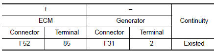
- Also check harness for short to power and short to ground.
Is the inspection result normal? YES >> GO TO 2.
NO >> Repair or replace error-detected parts.
2.REPLACE GENERATOR
- Replace generator. Refer to CHG-20, "Removal and Installation".
- Erase DTC.
- Perform DTC confirmation procedure again. Refer to EC-171, "DTC Description".
Is DTC detected again? YES >> Replace ECM. Refer to EC-499, "Removal and Installation".
NO >> INSPECTION END
 U1001 CAN comm circuit
Description
CAN (Controller Area Network) is a serial communication line for real time
application. It is an on-vehicle multiplex
communication line with high data communication speed and excellen ...
 U1044 ENG comm circuit
DTC Description
DTC DETECTION LOGIC
DTC No.
CONSULT screen terms
(Trouble diagnosis content)
DTC detecting condition
U1044
ENG COMM CIRCUIT
(Engine communication circu ...
Other materials:
Towing load/specification
TOWING LOAD/SPECIFICATION CHART
U.S. and Canada
Maximum Towing Capacity*1
1,100lb.
(500 kg)
Maximum Tongue Load
110 lb.
(50 kg)
Maximum Gross Combined Weight Rating
5,291 lb.
(2,400 kg)
*1: The towing capacity ...
Door outside lower molding
Exploded View
Rear door outside lower molding
Front door outside lower molding
Clip
Front
Removal and Installation
FRONT DOOR OUTSIDE LOWER MOLDING
Removal
Using a suitable tool (A) release clips from front door outside
lower molding (1) starting at the rear and work ...
ECU diagnosis information
CAN GATEWAY
Reference Value
VALUES ON THE DIAGNOSIS TOOL
NOTE:
The following table includes information (items) inapplicable to this vehicle.
For information (items) applicable
to this vehicle, refer to CONSULT display items.
DTC Index
...
