Nissan Rogue (T33) 2021-Present Service Manual: Turbocharger Boost Sensor
Component Inspection
CHECK TURBOCHARGER BOOST SENSOR
-
Turn ignition switch OFF.
-
Remove turbocharger boost sensor with its harness connector.
-
Install pressure pump (A) to turbocharger boost sensor (1).
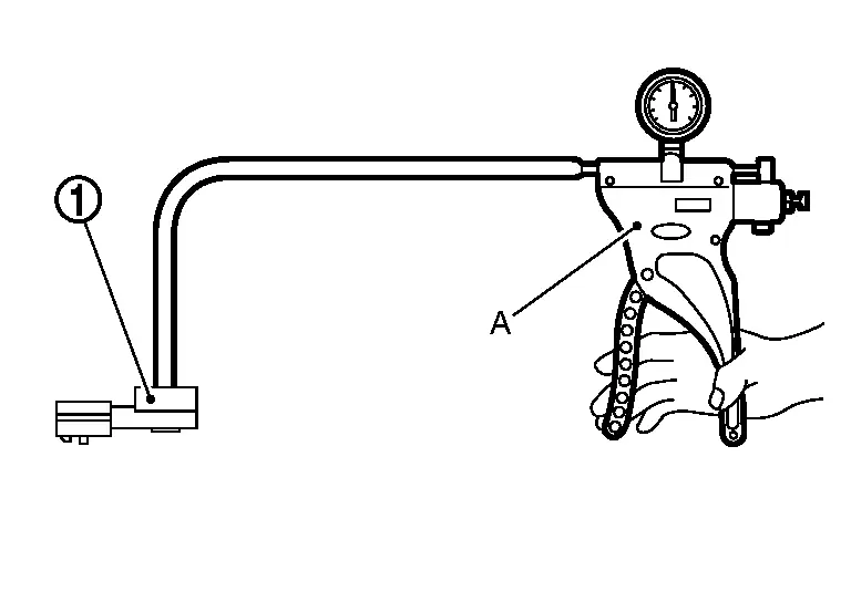
CAUTION:
When insert a pressure pump hose to the sensor, be careful to the damage of the sensor housing.
-
Turn ignition switch ON.
-
Check the voltage between ECM harness connector terminals as follows.
ECM Connector Terminal F71 81 107  NOTE:
NOTE:
The sensor is absolute pressure sensor, output value may differ depending on atmospheric pressure and altitude.
-
Measure the atmospheric pressure.
NOTE:
As the atmospheric pressure described on the synoptic chart is the value at sea level, compensate the pressure with the following chart.
Altitude (m) Compensated pressure (hPa) 0 0 200 ‚àí24 400 ‚àí47 600 ‚àí70 800 ‚àí92 1000 ‚àí114 1500 ‚àí168 2000 ‚àí218 -
Check the absolute pressure sensor value corresponding to the atmospheric pressure.
Atmospheric pressure (hPa) Voltage (V) 800 1.2 – 1.5 850 1.3 – 1.5 900 1.3 – 1.6 950 1.4 – 1.6 1000 1.4 – 1.7 1050 1.5 – 1.8 -
Confirm the difference of the absolute pressure sensor voltage between at atmospheric pressure condition and at the following pressurized condition.
NOTE:
-
Always calibrate the pressure pump gauge when using it.
-
Inspection should be done at room temperature [10 - 30°C (50 - 86°F)].
Condition [Pressure (Relative to atmospheric pressure)] Voltage difference
(Approx.)40 kPa (‚àí300 mmHg) + 0.5 V -
Is the inspection result normal?
YES>>INSPECTION END
NO>>Replace turbocharger boost sensor. Refer to Exploded View.
Other materials:
Dtc/circuit Diagnosis. U2a06-88 Comm Bus Off V-Fd
DTC Description
DESCRIPTIONCAN (Controller Area Network) is a serial
communication line for real time applications. It is an on-Nissan Ariya
vehicle multiplex communication line with high data communication speed
and excellent error detection ability. Modern Nissan Ariya vehicle is
equipped ...
Informations de base et fonctionnement
Exemple d'affichage dynamique
L’affichage tête haute (Head-Up Display ou HUD) du Nissan Rogue est une technologie de pointe conçue pour projeter les données de conduite essentielles directement dans votre champ de vision. Cette innovation permet au conducteur du Nissan Rogue de rester co ...
P0261 Fuel Injector (cylinder 1)
DTC Description
DTC DETECTION LOGIC DTC
CONSULT screen terms
(Trouble diagnosis content)
DTC detection condition
P0261
00
CYL1 INJECTOR
(Cylinder 1 Injector A Circuit Low)
Diagnosis condition
—
Signal (terminal)
—
Threshold
Direct injector driver unit ...