Nissan Rogue (T33) 2021-Present Service Manual: Trouble Diagnosis - Specification Value
Component Function Check
START
Make sure that all of the following conditions are satisfied.
-
Nissan Ariya Vehicle driven distance: More than 5,000 km (3,107 miles)
-
Atmospheric pressure: 98.3 - 104.3 kPa (0.98 - 1.04 bar, 1.003 - 1.064 kg/cm2, 14.25 - 15.12 psi)
-
Atmospheric temperature: 20 - 30°C (68 - 86°F)
-
Engine coolant temperature: 75 - 95°C (167 - 203°F)
-
Transmission: Warmed-up
-
After the engine is warmed up to normal operating temperature, drive Nissan Ariya vehicle until “ATF TEMP SEN” (CVT fluid temperature sensor signal) indicates more than 60°C (140°F).
-
-
Electrical load: Not applied*
-
Engine speed: Idle
*: Rear window defogger switch, air conditioner switch, lighting switch are OFF. Steering wheel is straight ahead.
>>
GO TO 2.
PERFORM “SPEC” of “DATA MONITOR” MODE
 With CONSULT
 NOTE:
NOTE:
Perform “SPEC” in “DATA MONITOR” mode in maximum scale display.
-
Refer to Work Procedure.
-
Select “DATA MONITOR” mode of “ENGINE” using CONSULT
-
Select “Reference” and change “DISPLAY TYPE” to “Line Graph”.
-
Select “Base fuel schedule”, “Air fuel ratio compensation (bank 1)” and “MASS AIR FLOW SENSOR (Hz) B1”.
-
Make sure that monitor items are within the SP value.
Is the inspection result normal?
YES>>END
NO>>Refer to Diagnosis Procedure.
Diagnosis Procedure
ECM input/output valve when the engine control system operates normally.
NOTE:
The SP value is indicated when “DISPLAY TYPE” is “Line Graph”.
When the indicated value of “DATA MONITOR” mode is within the SP value, the engine control system is confirmed OK. When the indicated value of “DATA MONITOR” mode is not within the SP value, the engine control system may have one or more malfunctions.
The SP value is used to detect malfunctions that may affect the Engine Control System, but will not light the MIL.
The SP value will be displayed for the following three items:
-
Base fuel schedule (The fuel injection pulse width programmed into ECM prior to any learned on board correction)
-
Air fuel ratio compensation (bank 1) (The mean value of air-fuel ratio feedback correction factor per cycle)
-
MASS AIR FLOW SENSOR (Hz) B1 (The signal frequency of the mass air flow sensor)
OVERALL SEQUENCE
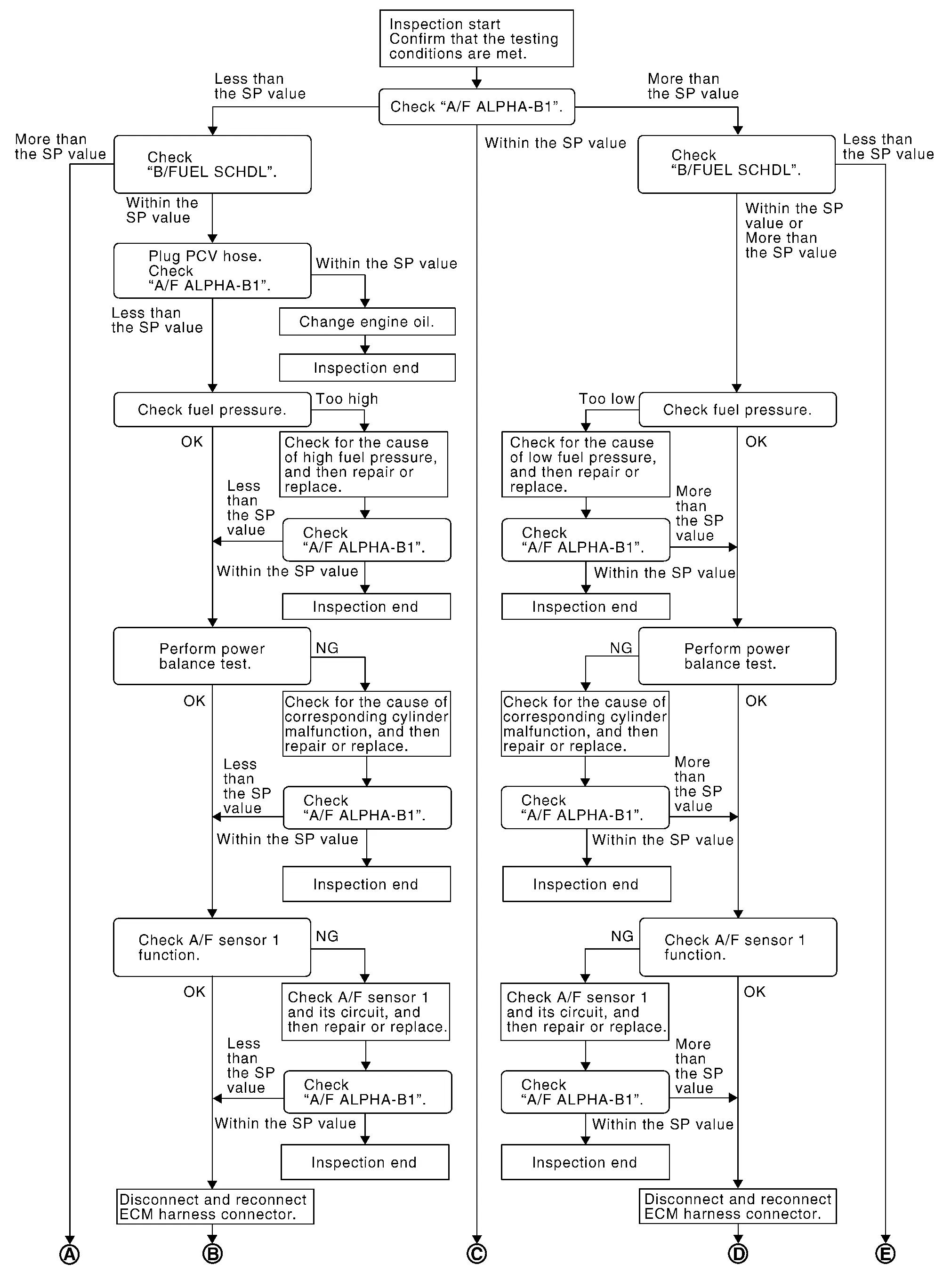
DETAILED PROCEDURE
CHECK “Air fuel ratio compensation (bank 1)”
With CONSULT
-
Start engine.
-
Confirm that the testing conditions are met. Refer to Component Function Check.
-
Select “DATA MONITOR” mode of “ENGINE” using CONSULT
-
Select “Reference” and change “DISPLAY TYPE” to “Line Graph”.
-
Select “Air fuel ratio compensation (bank 1)”.
NOTE:
Check “Air fuel ratio compensation (bank 1)” for approximately 1 minute because they may fluctuate. It is NG if the indication is out of the SP value even a little.
Is the measurement value within the SP value?
YES>>GO TO 17.
NO-1>>Less than the SP value: GO TO 2.
NO-2>>More than the SP value: GO TO 3.
CHECK “Base fuel schedule”
Select “Base fuel schedule” at “Reference” of “DATA MONITOR” mode, and make sure that the indication is within the SP value.
Is the measurement value within the SP value?
YES>>GO TO 4.
NO>>More than the SP value: GO TO 19.
CHECK “Base fuel schedule”
Select “Base fuel schedule” at “Reference” of “DATA MONITOR” mode, and make sure that the indication is within the SP value.
Is the measurement value within the SP value?
YES>>GO TO 6.
NO-1>>More than the SP value: GO TO 6.
NO-2>>Less than the SP value: GO TO 25.
CHECK “Air fuel ratio compensation (bank 1)”
-
Stop the engine.
-
Disconnect PCV hose, and then plug it.
-
Start engine.
-
Select “Air fuel ratio compensation (bank 1)” in “SPEC” of “DATA MONITOR” mode, and make sure that the indication is within the SP value.
Is the measurement value within the SP value?
YES>>GO TO 5.
NO>>GO TO 6.
CHANGE ENGINE OIL
-
Stop the engine.
-
Change engine oil.
NOTE:
This symptom may occur when a large amount of gasoline is mixed with engine oil because of driving conditions (such as when engine oil temperature does not rise enough since a journey distance is too short during winter). The symptom will not be detected after changing engine oil or changing driving condition.
>>
INSPECTION END
CHECK FUEL PRESSURE
Check fuel pressure. Refer to Work Procedure.
Is the inspection result normal?
YES>>GO TO 9.
NO-1>>Fuel pressure is too high: Replace “fuel filter and fuel pump assembly”, Refer to Removal and Installation and then GO TO 8.
NO-2>>Fuel pressure is too low: GO TO 7.
DETECT MALFUNCTIONING PART
Check fuel hoses and fuel tubes for clogging
Is the inspection result normal?
YES>>Replace “fuel filter and fuel pump assembly”, Refer to Removal and Installation and then GO TO 8.
NO>>Repair or replace and then GO TO 8.
CHECK “Air fuel ratio compensation (bank 1)”
-
Start engine.
-
Select “Air fuel ratio compensation (bank 1)” at “Reference” of “DATA MONITOR” mode, and make sure that the indication is within the SP value.
Is the measurement value within the SP value?
YES>>INSPECTION END
NO>>GO TO 9.
PERFORM POWER BALANCE TEST
-
Perform “POWER BALANCE” in “ACTIVE TEST” mode.
-
Make sure that the each cylinder produces a momentary engine speed drop.
Is the inspection result normal?
YES>>GO TO 12.
NO>>GO TO 10.
DETECT MALFUNCTIONING PART
Check the following.
-
Ignition coil and its circuit (Refer to Component Function Check.)
-
Direct fuel injector and its circuit (Refer to Diagnosis Procedure.)
-
Port fuel injector and its circuit (Refer to Diagnosis Procedure.)
-
Intake air leakage
-
Low compression pressure
Is the inspection result normal?
YES>>Replace malfunctioning fuel injector, Refer to Exploded View, and then GO TO 11.
NO>>Repair or replace malfunctioning part and then GO TO 11.
CHECK “A/F ALPHA-B1”
-
Start engine.
-
Select “A/F ALPHA-B1” at “Reference” of “DATA MONITOR” mode, and make sure that the indication is within the SP value.
Is the measurement value within the SP value?
YES>>INSPECTION END
NO>>GO TO 12.
CHECK A/F SENSOR 1 FUNCTION
Perform all DTC CONFIRMATION PROCEDURE related with A/F sensor 1.
-
For DTC P0130, Refer to DTC Description.
-
For DTC P0131, Refer to DTC Description.
-
For DTC P0132, Refer to DTC Description.
-
For DTC P014C, Refer to DTC Description.
-
For DTC P014D, Refer to DTC Description.
-
For DTC P2096, Refer to DTC Description.
-
For DTC P2097, Refer to DTC Description.
Is any DTC detected?
YES>>GO TO 15.
NO>>GO TO 13.
CHECK A/F SENSOR 1 CIRCUIT
Perform DIAGNOSTIC PROCEDURE according to corresponding DTC.
>>
GO TO 14.
CHECK “A/F ALPHA-B1”
-
Start engine.
-
Select “A/F ALPHA-B1” at “Reference” of “DATA MONITOR” mode, and make sure that the each indication is within the SP value.
Is the measurement value within the SP value?
YES>>INSPECTION END
NO>>GO TO 15.
DISCONNECT AND RECONNECT ECM HARNESS CONNECTOR
-
Stop the engine.
-
Disconnect ECM harness connector. Check pin terminal and connector for damage, and then reconnect it.
>>
GO TO 16.
CHECK “A/F ALPHA-B1”
-
Start engine.
-
Select “A/F ALPHA-B1” at “Reference” of “DATA MONITOR” mode, and make sure that the indication is within the SP value.
Is the measurement value within the SP value?
YES>>INSPECTION END
NO>>Detect malfunctioning part. Refer to Symptom Table.
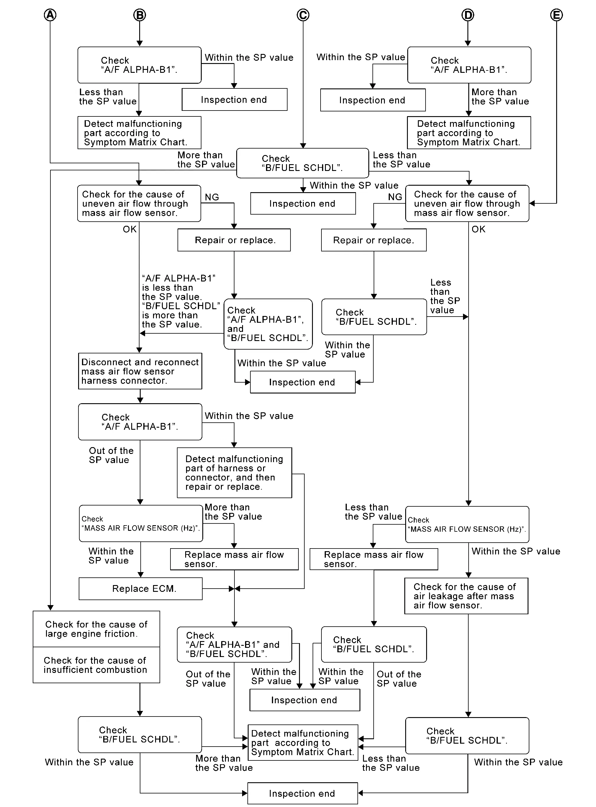
CHECK “B/FUEL SCHDL”
Select “B/FUEL SCHDL” at “Reference” of “DATA MONITOR” mode, and make sure that the indication is within the SP value.
Is the measurement value within the SP value?
YES>>INSPECTION END
NO-1>>More than the SP value: GO TO 18.
NO-2>>Less than the SP value: GO TO 25.
DETECT MALFUNCTIONING PART
-
Check for the cause of large engine friction. Refer to the following.
-
Engine oil level is too high
-
Engine oil viscosity
-
Belt tension of power steering, alternator, A/C compressor, etc. is excessive
-
Noise from engine
-
Noise from transmission, etc.
-
-
Check for the cause of insufficient combustion. Refer to the following.
-
Valve clearance malfunction
-
Intake valve timing control function malfunction
-
Camshaft sprocket installation malfunction, etc.
-
>>
Repair or replace malfunctioning part, and then GO TO 30.
CHECK INTAKE SYSTEM
Check for the cause of uneven air flow through mass air flow sensor. Refer to the following.
-
Crushed air ducts
-
Malfunctioning seal of air cleaner element
-
Uneven dirt of air cleaner element
-
Improper specification of intake air system
Is the inspection result normal?
YES>>GO TO 21.
NO>>Repair or replace malfunctioning part, and then GO TO 20.
CHECK “A/F ALPHA-B1”, AND “B/FUEL SCHDL”
Select “A/F ALPHA-B1” and “B/FUEL SCHDL” at “Reference” of “DATA MONITOR” mode, and make sure that the each indication is within the SP value.
Is the measurement value within the SP value?
YES>>INSPECTION END
NO>>“B/FUEL SCHDL” is more, “A/F ALPHA-B1” is less than the SP value: GO TO 21.
DISCONNECT AND RECONNECT MASS AIR FLOW SENSOR HARNESS CONNECTOR
-
Stop the engine.
-
Disconnect mass air flow sensor harness connector. Check pin terminal and connector for damage and then reconnect it again.
>>
GO TO 22.
CHECK “A/F ALPHA-B1”
-
Start engine.
-
Select “A/F ALPHA-B1” at “Reference” of “DATA MONITOR” mode, and make sure that the indication is within the SP value.
Is the measurement value within the SP value?
YES>>Detect malfunctioning part of mass air flow sensor circuit and repair it. Refer to DTC Index. Then GO TO 29.
NO>>GO TO 23.
CHECK “MASS AIR FLOW SENSOR (HZ) B1”
Select “MASS AIR FLOW SENSOR (HZ) B1” at “Reference” of “DATA MONITOR” mode, and make sure that the indication is within the SP value.
Is the measurement value within the SP value?
YES>>GO TO 24.
NO>>More than the SP value: Replace mass air flow sensor, Refer to Exploded View, and then GO TO 29.
REPLACE ECM
Replace ECM. Refer to ECM : Removal & Installation.
>>
GO TO 29.
CHECK INTAKE SYSTEM
Check for the cause of uneven air flow through mass air flow sensor. Refer to the following.
-
Crushed air ducts
-
Malfunctioning seal of air cleaner element
-
Uneven dirt of air cleaner element
-
Improper specification of intake air system
Is the inspection result normal?
YES>>GO TO 27.
NO>>Repair or replace malfunctioning part, and then GO TO 26.
CHECK “B/FUEL SCHDL”
Select “B/FUEL SCHDL” at “Reference” of “DATA MONITOR” mode, and make sure that the indication is within the SP value.
Is the measurement value within the SP value?
YES>>INSPECTION END
NO>>Less than the SP value: GO TO 27.
CHECK “MASS AIR FLOW SENSOR (HZ) B1”
Select “MASS AIR FLOW SENSOR (HZ) B1” at “Reference” of “DATA MONITOR” mode, and make sure that the indication is within the SP value.
Is the measurement value within the SP value?
YES>>GO TO 28.
NO>>Less than the SP value: Replace mass air flow sensor, Refer to Exploded View, and then GO TO 30.
CHECK INTAKE SYSTEM
Check for the cause of air leak after the mass air flow sensor. Refer to the following.
-
Disconnection, looseness, and cracks in air duct
-
Looseness of oil filler cap
-
Disconnection of oil level gauge
-
Open stuck, breakage, hose disconnection, or cracks of PCV valve
-
Disconnection or cracks of EVAP purge hose, open stuck of EVAP canister purge volume control solenoid valve
-
Malfunctioning seal of rocker cover gasket
-
Disconnection, looseness, or cracks of hoses, such as vacuum hose, connecting to intake air system parts
-
Malfunctioning seal of intake air system, etc.
>>
GO TO 30.
CHECK “A/F ALPHA-B1” AND “B/FUEL SCHDL”
Select “A/F ALPHA-B1” and “B/FUEL SCHDL” at “Reference” of “DATA MONITOR” mode, and make sure that the indication is within the SP value.
Is the measurement value within the SP value?
YES>>INSPECTION END
NO>>Detect malfunctioning part. Refer to Symptom Table.
CHECK “B/FUEL SCHDL”
Select “B/FUEL SCHDL” at “Reference” of “DATA MONITOR” mode, and then make sure that the indication is within the SP value.
Is the measurement value within the SP value?
YES>>INSPECTION END
NO>>Detect malfunctioning part. Refer to Symptom Table.
Other materials:
System Description. Component Parts. Drive Mode System
Drive Mode System
Component Parts Location
No. Component Function
1.
Drive mode select switch
Refer to Drive Mode Select Switch.
2.
Chassis control module
Chassis control module controls the drive mode select system.
Refer to Component Parts Location (without ProPILOT Assi ...
How to Use This Manual
Description
This volume explains “Removal, Disassembly, Installation, Inspection and Adjustment” and “Trouble Diagnoses”.
Terms
The captions WARNING and CAUTION warn you of steps that must be followed to prevent personal injury and/or damage to some part of the Nissan Ariya vehicle.
...
C10b4-98 Overheat
DTC Description
DTC DETECTION LOGIC DTC No.
CONSULT screen terms
(Trouble diagnosis content) DTC detection condition
C10B4
98
Overheat
(Overheat)
Diagnosis condition
When ignition switch is ON
Signal (terminal)
—
Threshold
System is high temperature status.
...