Nissan Rogue Service Manual: The door open warning continues displaying, or does not display
Description
- The door open warning is displayed even though all of the doors are closed.
- The door open warning is not displayed even though a door is ajar.
Diagnosis Procedure
1.CHECK BCM INPUT SIGNAL
Check the BCM input signal. Refer to DLK-149, "Component Function Check" (with Intelligent Key system) or DLK-319, "Component Function Check" (without Intelligent Key system).
Is the inspection result normal? YES >> GO TO 2.
NO >> GO TO 3.
2.CHECK COMBINATION METER INPUT SIGNAL
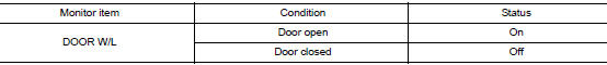
Select the "METER/M&A" "Data Monitor" and check the "DOOR W/L" monitor value while opening and closing the door.
Is the inspection result normal? YES >> Replace combination meter. Refer to MWI-82, "Removal and Installation".
NO >> Replace BCM. Refer to BCS-75, "Removal and Installation" (with Intelligent Key system) or BCS- 135, "Removal and Installation" (without Intelligent Key system).
3.CHECK DOOR SWITCH SIGNAL CIRCUIT
Check the door switch signal circuit. Refer to DLK-149, "Diagnosis Procedure" (with Intelligent Key system) or DLK-319, "Diagnosis Procedure" (without Intelligent Key system).
Is the inspection result normal? YES >> GO TO 4.
NO >> Repair or replace harness or connector.
4.CHECK DOOR SWITCH
Check the door switch. Refer to DLK-150, "Component Inspection" (with Intelligent Key system) or DLK-320, "Component Inspection" (without Intelligent Key system).
Is the inspection result normal? YES >> Replace combination meter. Refer to MWI-82, "Removal and Installation".
NO >> Replace applicable door switch. Refer to DLK-269, "Removal and Installation" (with Intelligent Key system) or DLK-385, "Removal and Installation" (without Intelligent Key system).
 The low washer fluid warning continues displaying, or
does not display
The low washer fluid warning continues displaying, or
does not display
Description
The warning is still displayed even after washer fluid is added.
The warning is not displayed even though the washer tank is empty.
Diagnosis Procedure
1.CHECK WASHER FLUID LEVEL ...
 The liftgate open warning continues displaying, or does
not display
The liftgate open warning continues displaying, or does
not display
Description
The liftgate open warning is displayed continuously even though the
liftgate is closed.
The liftgate open warning is not displayed even though the
liftgate is open.
Di ...
Other materials:
Unit disassembly and assembly
CENTER CONSOLE ASSEMBLY
Exploded View
Center console cup holder (without
heated seats)
Coin tray insert
Center console cup holder (with
heated seats)
Front heated seat switch (RH)
Front heated seat switch (LH)
Shift selector finisher
Shift selector ...
System description
COMPONENT PARTS
Component Parts Location
Right rear wheel area
Instrument panel
Engine compartment
Left side of instrument panel (view
with trim panel removed)
No.
Part
Function
1
Optical sensor
Refer to EXL-10, "Optical Sensor" ...
Front grille
Exploded View
Front bumper fascia
Front camera (if equipped)
Front grille
Front emblem
Pawl
Clip
Removal and Installation
REMOVAL
Remove front grille upper clip (A) (LH/RH).
Release clips and pawls, then remove front grille.
: Clip
: Pawl
Disco ...
