Nissan Rogue Service Manual: Unit disassembly and assembly
CENTER CONSOLE ASSEMBLY
Exploded View
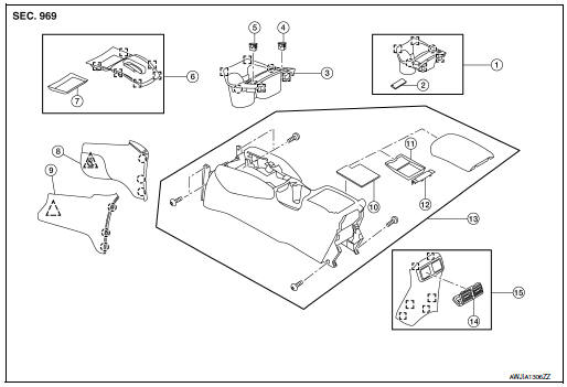
- Center console cup holder (without heated seats)
- Coin tray insert
- Center console cup holder (with heated seats)
- Front heated seat switch (RH)
- Front heated seat switch (LH)
- Shift selector finisher
- Shift selector finisher mat
- Center console side finisher (RH)
- Center console side finisher (LH)
- Center console bin mat
- Center console tray
- Center console rear brace finisher
- Center console assembly
- Rear center ventilator grille
- Center console rear finisher
 Metal clip
 Clip
Clip
 Pawl
Pawl
Disassembly and Assembly
DISASSEMBLY
- Remove center console assembly. Refer to IP-18, "Removal and Installation".
- Remove the center console bin mat. Refer to IP-25, "Exploded View".
- Release clips using a suitable tool and remove shift selector
finisher.: Metal clip
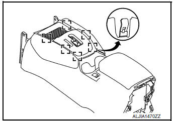
- Release clips and pawls using a suitable tool and remove center console cup holder.
: Metal clip
: Pawl
- Release pawls and remove center console rear brace finisher. Refer to IP-25, "Exploded View".
- Remove screws and center console tray. Refer to IP-25, "Exploded View".
ASSEMBLY
Assembly is in the reverse order of disassembly.
 Glove box assembly and housing
Removal and Installation
REMOVAL
Release instrument side finisher (RH) (1) pawls using a suitable
tool and remove.
: Pawl
NOTE:
LH side shown; RH similar.
Release the glove box ...
 Seat
Seat
...
Other materials:
P0605 ECM
DTC Description
DTC DETECTION LOGIC
DTC No.
CONSULT screen terms
(Trouble diagnosis content)
DTC detecting condition
P0605
ECM
[Internal control module read only memory
(ROM) error]
Malfunction in the internal ROM of ECM.
POSSIBLE CAUSE
ECM
FAIL-SAFE
T ...
System
FRONT WIPER AND WASHER SYSTEM
FRONT WIPER AND WASHER SYSTEM : System Diagram
FRONT WIPER AND WASHER SYSTEM : System Description
OUTLINE
FRONT WIPER CONTROL (BASIC)
BCM detects the combination switch position by the combination
switch reading function.
BCM transmits the f ...
Diagnosis and repair work flow
Work Flow
DETAILED FLOW
1.INTERVIEW FROM THE CUSTOMER
Clarify customer complaints before inspection. First of all, perform an
interview utilizing BRC-67, "Diagnostic
Work Sheet" and reproduce the symptom as well as fully understand it. Ask
customer about his/her complaints
careful ...
