Nissan Rogue Service Manual: Glove box assembly and housing
Removal and Installation
REMOVAL
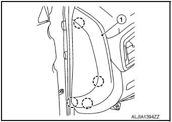
- Release instrument side finisher (RH) (1) pawls using a suitable tool and remove.
 : Pawl
NOTE: LH side shown; RH similar.
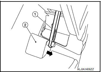
- Release the glove box damper (1) from the glove box assembly (2) as shown.
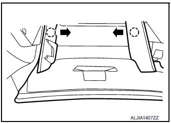
- Release the glove box assembly pawls as shown.
: Pawl
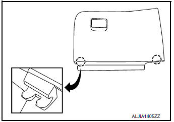
- Release the pawls and remove the glove box assembly.: Pawl
- Remove instrument finisher E. Refer to IP-16, "INSTRUMENT FINISHER E : Removal and Installation".
- Remove audio unit (DISPLAY AUDIO). Refer to AV-64, "Removal and Installation"
- Remove AV control unit. Refer to AV-209, "Removal and Installation" (NAVIGATION WITHOUT BOSE) or AV-376, "Removal and Installation" (NAVIGATION WITH BOSE).
- Remove front air control or A/C switch assembly. Refer to HAC-181, "Removal and Installation" (MANUAL AIR CONDITIONING) or HAC-102, "Removal and Installation" (AUTOMATIC AIR CONDITIONING).
- . Remove the glove box housing screws (A).
- Release the clips using a suitable tool, disconnect the harness
connector and remove glove box housing.
 : Metal clip
INSTALLATION
Installation is in the reverse order of removal.
 Instrument lower panel LH
Removal and Installation
REMOVAL
Release instrument side finisher (LH) (1) pawls using a suitable
tool and remove.
: Pawl
Remove bolts (A) and fuel filler lid/hood lock release ...
 Unit disassembly and assembly
CENTER CONSOLE ASSEMBLY
Exploded View
Center console cup holder (without
heated seats)
Coin tray insert
Center console cup holder (with
heated seats)
Front heated ...
Other materials:
Speedometer and odometer
Speedometer
The speedometer indicates vehicle speed.
Odometer/Twin trip odometer
The odometer 1 and the twin trip odometer 2
are displayed below the Vehicle Information Display
when the ignition switch is placed in the ON
position.
The odometer records the total distance the vehicle
has ...
Exhaust gas (carbon monoxide)
WARNING
Do not breathe exhaust gases; they
contain colorless and odorless carbon
monoxide. Carbon monoxide is dangerous.
It can cause unconsciousness or
death.
If you suspect that exhaust fumes are
entering the vehicle, drive with all windows
fully ...
Difference between predicted and actual
distances
Backing up on a steep uphill
When backing up the vehicle up a hill, the distance
guide lines and the vehicle width guide
lines are shown closer than the actual distance.
For example, the display shows 3 ft (1.0 m) to the
place A , but the actual 3 ft (1.0 m) distance on
the hill is the p ...
