Nissan Rogue (T33) 2021-Present Service Manual: System Description :: System
System Description
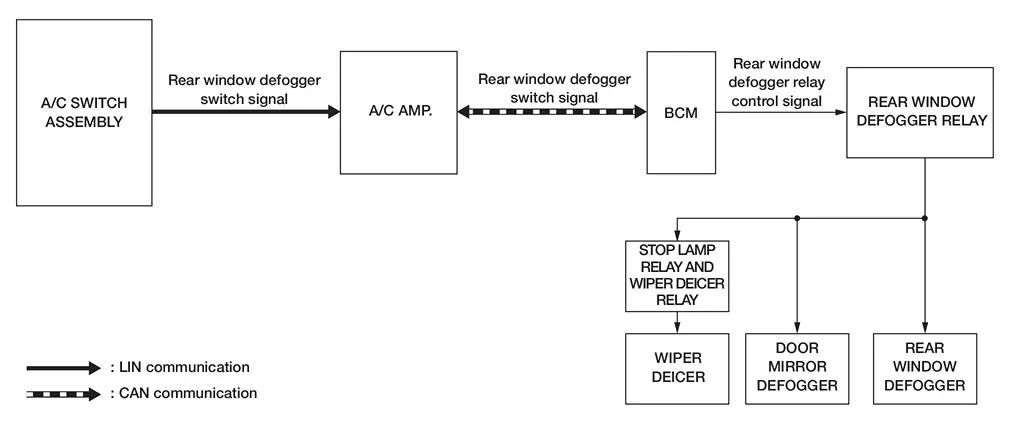
SYSTEM DIAGRAM
INPUT/OUTPUT SIGNAL CHART
| Switch | Input signal to BCM | BCM function | Actuator |
|---|---|---|---|
| Rear window defogger switch | Defogger switch signal | Rear window defogger control | Rear window defogger |
OPERATION DESCRIPTION
-
Turn rear window defogger switch ON when the engine running. Then A/C switch assembly transmits rear window defogger switch signal to A/C amp. via LIN communication line.
-
A/C amp. transmits rear window defogger request signal to BCM via CAN communication.
-
BCM turns rear window defogger relay, and wiper deicer relay, ON and transmits rear window defogger feedback signal to A/C amp. via CAN communication when rear window defogger request signal is received.
-
Rear window defogger, door mirror defogger, and wiper deicer are supplied with power and operate when rear window defogger relay and wiper deicer relay turns ON.
-
A/C amp. transmit rear window defogger feedback signal to A/C switch assembly via LIN communication line when rear window defogger feedback signal is received.
-
A/C switch assembly turns on the rear window defogger indicator lamp when rear window defogger feedback signal is received.
-
When remote engine start function is operated, according to the Nissan Ariya vehicle situation* A/C amp. transmits the rear window defogger request signal to BCM via CAN communication. For details, refer to Remote Engine Start Control.
 NOTE:
NOTE:
*: Depending on the Nissan Ariya vehicle situation (ambient temperature, in-vehicle temperature and sunload etc.) it is not operated.
TIMER FUNCTION
-
BCM turns rear window defogger relay, and wiper deicer relay, ON for approximately 20 minutes when rear window defogger switch turns ON. It makes rear window defogger, door mirror defogger, and wiper deicer, operate.
-
Timer is canceled after pressing rear window defogger switch again during timer operation. Then BCM turns rear window defogger relay, and wiper deicer relay, OFF. The same reaction also occurs during timer operation, if the ignition switch is turned OFF.
Other materials:
Symptom Diagnosis. Door Does Not Lock/unlock with Door Request Switch and Intelligent Key
Description
All doors do not lock/unlock using door request switch.SYMPTOM TABLE (BOTH INTELLIGENT KEYS HAVE THE SAME SYMPTOMS) Door lock operation (remote keyless entry)
Door lock operation (request switch of front/rear/back door) or
trunk/back door open operation (opener switch of trunk/back ...
Bcm
CONSULT Function (BCM - BCM)
DATA MONITORNOTE:
The following table includes information [items]
inapplicable to this Nissan Ariya vehicle. For information [items]
applicable to this vehicle, refer to CONSULT display items.
Monitor item
[Unit] Description
Door switch assist
[Off/On]
...
Differential Side Oil Seal
Exploded View
1.
Transaxle assembly
2.
Differential side oil seal (left side)
3.
Differential side oil seal (right side)
: Always replace after every disassembly.
: Apply CVT fluid.
1.
Transaxle assembly
2.
Differential side oil seal (left side)
...