Nissan Rogue (T33) 2021-Present Service Manual: System Description :: Component Parts. Defogger System
Defogger System
Component Parts Location
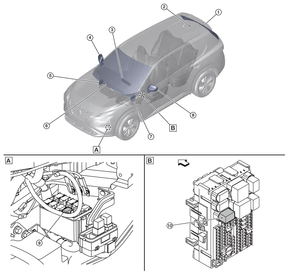
| A. | View of engine compartment lower left | B. | View of Fuse block (J/B) (fuse block (J/B) removed) | Nissan Ariya Vehicle front |
| No. | Component | Function |
|---|---|---|
| 1. | Rear window defogger | Refer to Rear Window Defogger. |
| 2. | Rear window defogger condenser | Reduce the noise of rear window defogger operation. |
| 3. |
AC switch assembly (Rear window defogger switch) |
|
| 4. | Door mirror RH (mirror defogger) (if so equipped) | Refer to Door Mirror Defogger. |
| 5. | A/C amp. |
|
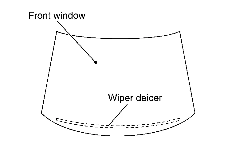
| 6. | Wiper deicer (if so equipped) | Refer to Wiper Deicer. |
| 7. | BCM (Body Control Module) |
|
| 8. | Door mirror LH (mirror defogger) (if so equipped) | Refer to Door Mirror Defogger. |
| 9. | Stop lamp relay and wiper deicer relay (wiper deicer relay) (if so equipped) | Operates the wiper deicer with the control signal from BCM. |
| 10. | Rear window defogger relay | Operates the rear window defogger, door mirror defogger and the wiper deicer with the control signal from BCM. |
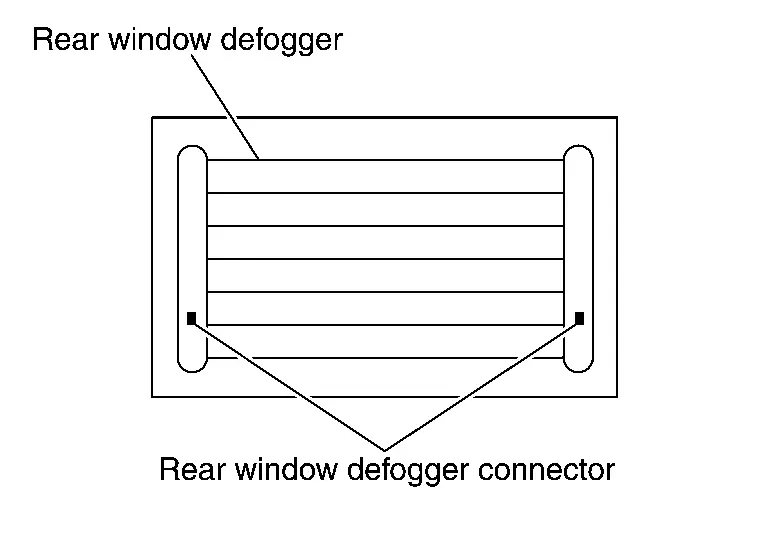
Rear Window Defogger
COMPONENT FUNCTION WITHIN SYSTEM
Heats the heating wire with the power supply from the rear window defogger relay to prevent the rear window from fogging up.
INDIVIDUAL COMPONENT FUNCTION
Heats the heating wire.
COMPONENT OPERATION
When the rear window defogger switch is turned ON, current flows to the rear window defogger, heating the heat wires.
COMPONENT PARTS LOCATION
Contained inside the back door window glass.
Refer to Component Parts Location.
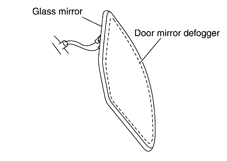
Door Mirror Defogger
COMPONENT FUNCTION WITHIN SYSTEM
Heats the heating wire with the power supply from the rear window defogger relay to prevent the door mirror from fogging up.
INDIVIDUAL COMPONENT FUNCTION
Heats the heating wire.
COMPONENT OPERATION
When the rear window defogger switch is turned ON, current flows to the mirror defogger, heating the heat wires.
COMPONENT PARTS LOCATION
Contained inside the glass mirror.
Refer to Component Parts Location.
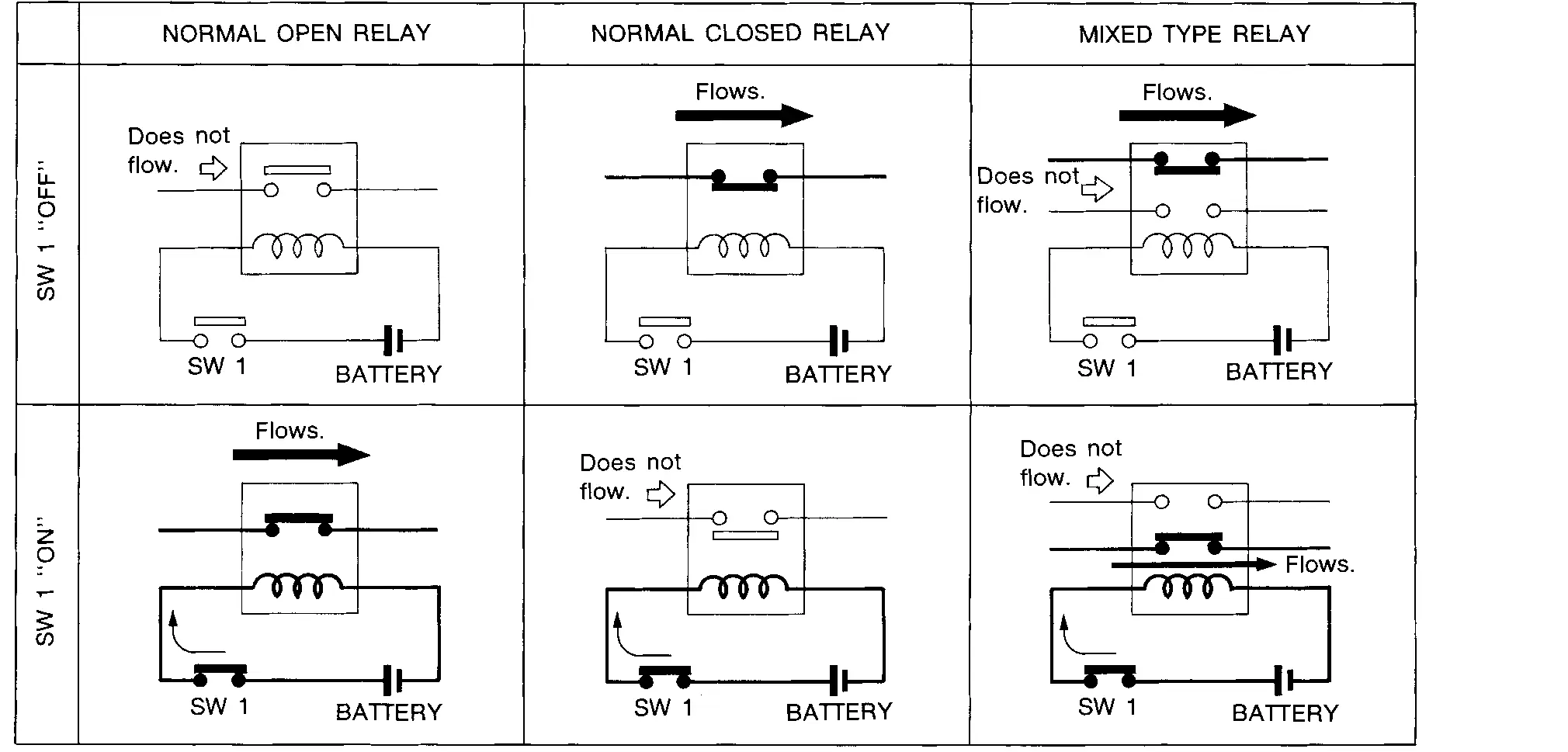
Rear Window Defogger Relay
COMPONENT FUNCTION WITHIN SYSTEM
This relay activates according to the rear window defogger relay control signal that is controlled by BCM, and activates the defogger system.
INDIVIDUAL COMPONENT FUNCTION
It turns the relay switch ON/OFF and sends a current from the battery to the defogger system.
COMPONENT OPERATION
The rear window defogger relay utilizes a normal open relay.
COMPONENT PARTS LOCATION
The rear window defogger relay is installed to the fuse block (J/B).
Refer to Component Parts Location.
Wiper Deicer
Heats the heating wire with the power supply from the wiper deicer relay to thaw by heating of wiper blade and glass.
Other materials:
How to Use This Manual. Recommended Chemical Products and Sealants
Recommended Chemical Products and Sealants
Refer to the following chart for help in selecting the appropriate chemical product or sealant. Product Description Purpose Nissan North America Part No. (USA) Nissan Canada Part No. (Canada) Aftermarket Cross-reference Part Nos.
1
Rear Vie ...
Manual Air Conditioning. Precaution. Precautions
Precautions
Precaution for Supplemental Restraint System (SRS) "AIR BAG" and "SEAT BELT PRE-TENSIONER"
The Supplemental Restraint System such as ŌĆ£AIR BAGŌĆØ and ŌĆ£SEAT BELT
PRE-TENSIONERŌĆØ, used along with a front seat belt, helps to reduce the
risk or severity of injury to the driver and ...
System Description. System
Srs Air Bag Control System
System Description
SYSTEM DIAGRAM Component Function
Occupant detection system sensor
Refer to Occupant Detection System Sensor.
Occupant detection system control unit
Refer to Occupant Detection System Control Unit.
Crash zone sensor
Refer to Cras ...