Nissan Rogue (T33) 2021-Present Service Manual: System Description :: System
Interior Room Lamp Control System
System Description
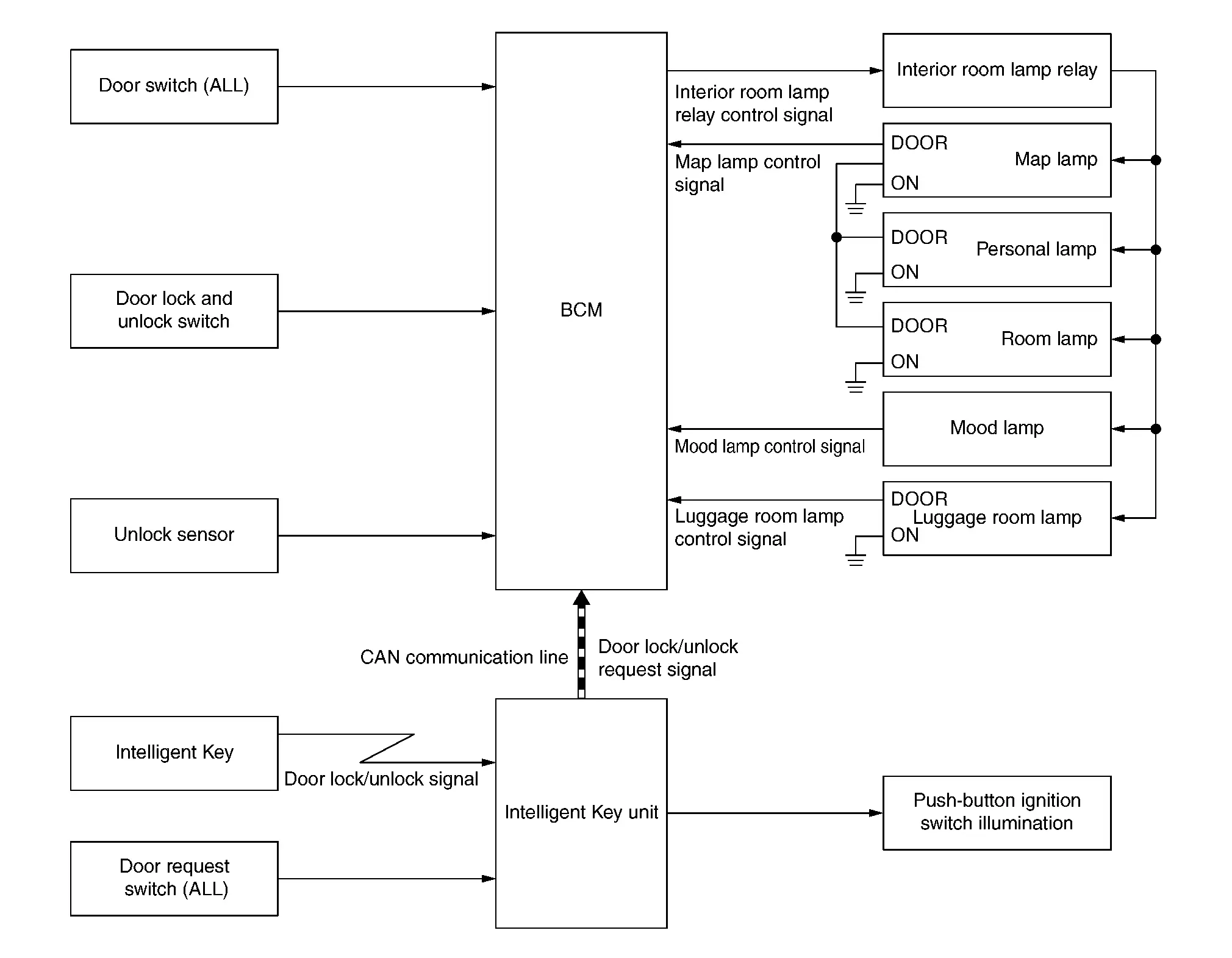
SYSTEM DIAGRAM
| Component | Function |
|---|---|
| Door switch (ALL) | Detects the door condition (open or close), and transmits the door switch signal to the BCM. |
| Door lock and unlock switch | Transmits the door lock and unlock switch signal to the BCM from door lock and unlock switch operation. |
| Unlock sensor | Detects front door LH lock condition, and transmits the unlock sensor signal to the BCM. |
| Intelligent Key | Transmits the door lock/unlock signal to the Intelligent Key unit from door lock/unlock button operation. |
| Door request switch (ALL) | Detects door lock/unlock operation from outside of the Nissan Ariya vehicle, and transmits the door request switch signal to the Intelligent Key unit. |
| BCM | Controls the interior room lamp relay, and turns each interior room lamp ON/OFF. |
| Intelligent Key unit |
|
| Interior room lamp relay | Interior room lamp relay supplies power supply voltage to each interior room lamp according to the control signal from the BCM. |
| Map lamp | Refer to Bulb Specifications. |
| Personal lamp | |
| Room lamp | |
| Mood lamp | |
| Luggage room lamp | |
| Push-button ignition switch illumination |
OUTLINE
-
The following interior room lamps are controlled by interior room lamp timer control function of BCM:
-
Map lamp*
-
Personal lamp*
-
Room lamp*
-
-
Mood lamp is controlled by mood lamp control function of BCM.
-
Luggage room lamp is controlled by luggage room lamp control function of BCM.
-
Push-button ignition switch illumination is controlled by push-button ignition switch illumination control function of Intelligent Key unit.
*: Interior room lamp timer control operates when the switch position is DOOR.
SIGNAL TRANSMISSION FUNCTION LIST
| Signal name | Input | Output | Description |
|---|---|---|---|
| Door switch signal | Door switch (ALL) | BCM | Transmits the door switch signal to the BCM. |
| Door lock and unlock switch signal | Door lock and unlock switch | BCM | Transmits the door lock and unlock switch signal to the BCM. |
| Unlock sensor signal | Unlock sensor | BCM | Transmits the unlock sensor signal to the BCM. |
| Door request switch signal | Door request switch (ALL) | Intelligent Key unit | Transmits the door request switch signal to the BCM. |
| Door lock/unlock request signal | Intelligent Key unit | BCM (CAN) | Transmits the door lock/unlock request signal via CAN communication. |
INTERIOR ROOM LAMP TIMER CONTROL
Interior Room Lamp Timer Basic Operation
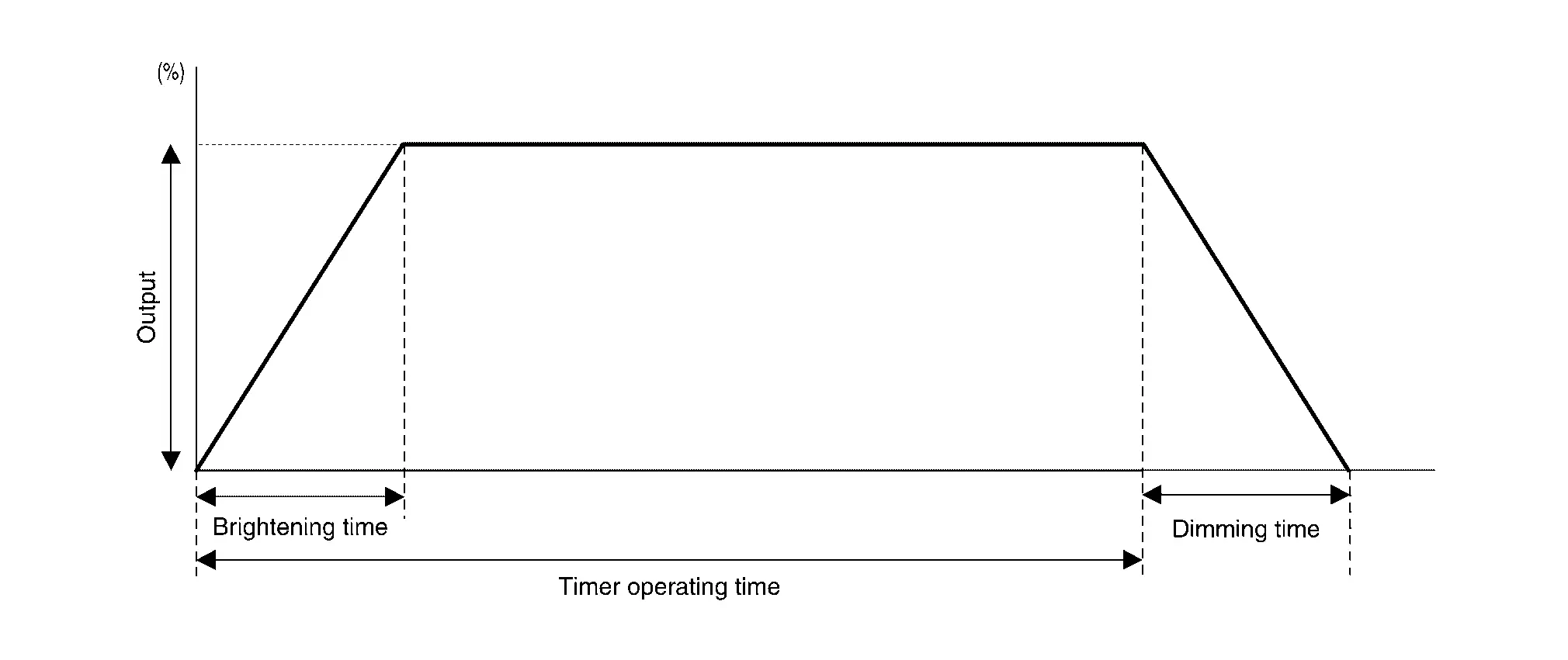
-
Interior room lamps turn ON and OFF (gradual brightening and dimming) by the interior room lamp timer.
-
Timer operating time is 20 seconds.
-
Brightening time is 2.8 second and dimming time is 1.5 seconds.
-
BCM judges the Nissan Ariya vehicle condition with the following items and activates the interior room lamp timer:
-
Ignition switch status
-
Door switch signal
-
Door lock and unlock switch signal
-
Unlock sensor signal
-
Door lock/unlock signal
-
Door lock/unlock request signal
-
Interior Room Lamp ON Operation
-
BCM always turns the interior room lamp relay ON to turn on interior room lamp when any door opens (except back door).
-
BCM activates interior room lamp timer in any of the following condition to turn interior room lamp ON for a period of time:
-
Status of all doors are OPEN –> CLOSE
-
Ignition switch is placed engine running –> OFF
-
Door unlock signal is detected when all doors close with ignition switch OFF
-
 NOTE:
NOTE:
The timer restarts if new condition is input during the timer operating time.
Interior Room Lamp OFF Operation
BCM stops the timer in any of the following condition to turn the interior room lamp OFF:
-
The timer operating time is expired
-
Ignition switch is placed OFF –> engine running
-
Door lock signal is detected with all doors closed with ignition switch OFF
MOOD LAMP CONTROL
-
BCM turns the mood lamp ON when any door (except back door) is opened or any door is unlocked (except back door).
-
BCM turns dimming operation of the mood lamp ON with the engine running.
-
BCM turns the mood lamp OFF when the doors are locked.
LUGGAGE ROOM LAMP CONTROL
-
BCM turns the luggage room lamp ON when back door is open (back door switch is ON).
-
BCM turns the luggage room lamp OFF when back door is close (back door switch is OFF).
PUSH-BUTTON IGNITION SWITCH ILLUMINATION CONTROL
-
BCM turns the push-button ignition switch illumination ON when ignition switch is ON.
-
BCM turns the push-button ignition switch illumination OFF when ignition switch is OFF.
Interior Room Lamp Battery Saver System
System Description
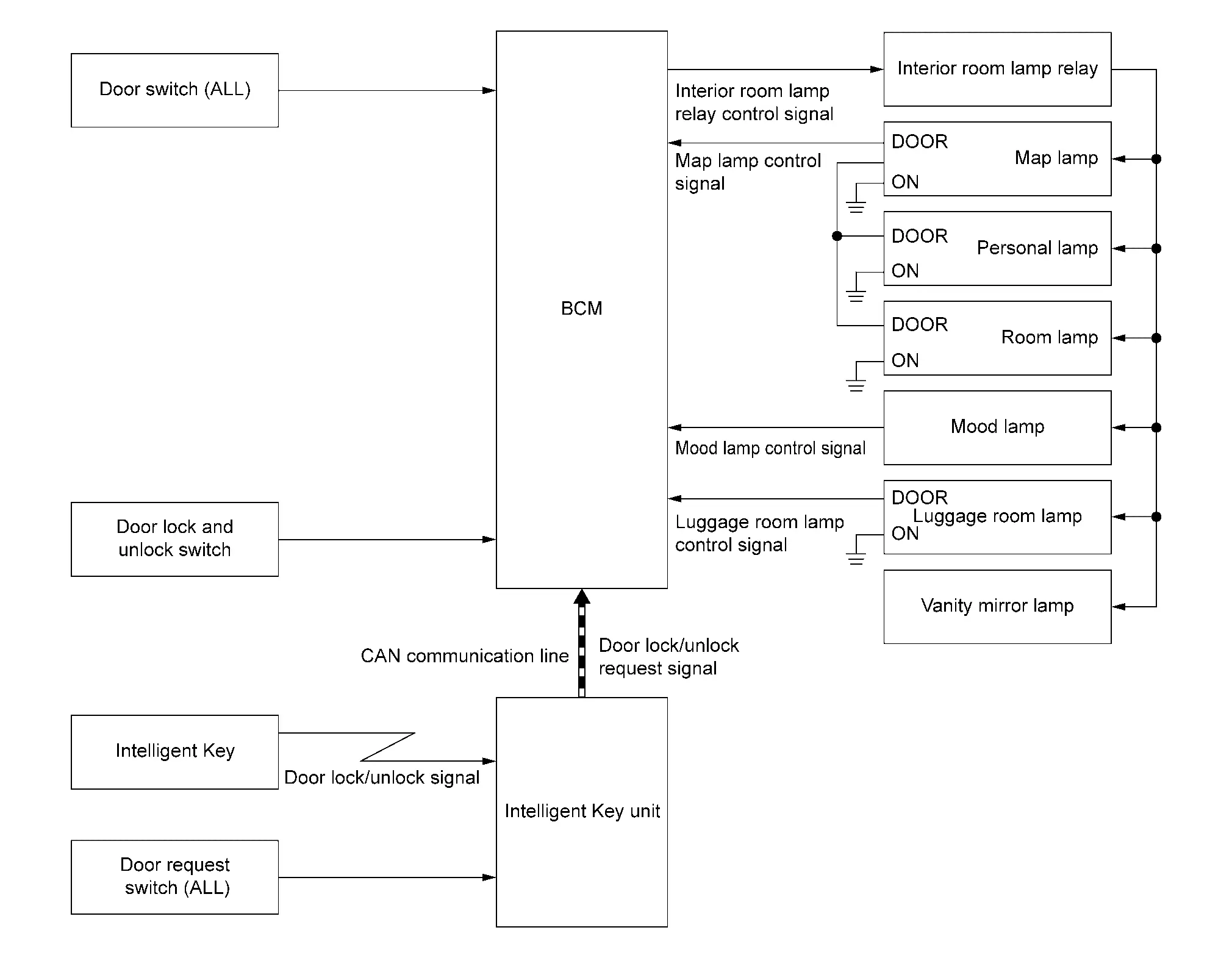
SYSTEM DIAGRAM
| Component | Function |
|---|---|
| Door switch (ALL) | Detects the door condition (open or close), and transmits the door switch signal to the BCM. |
| Door lock and unlock switch | Transmits the door lock and unlock switch signal to the BCM from door lock and unlock switch operation. |
| Unlock sensor | Detects front door LH lock condition, and transmits the unlock sensor signal to the BCM. |
| Intelligent Key | Transmits the door lock/unlock signal to the Intelligent Key unit from door lock/unlock button operation. |
| Door request switch (ALL) | Detects door lock/unlock operation from outside of the Nissan Ariya vehicle, and transmits the door request switch signal to the Intelligent Key unit. |
| BCM | Controls the interior room lamp relay, and turns each interior room lamp ON/OFF. |
| Intelligent Key unit |
|
| Interior room lamp relay | Interior room lamp relay supplies power supply voltage to each interior room lamp according to the control signal from the BCM. |
| Map lamp | Refer to Bulb Specifications. |
| Personal lamp | |
| Room lamp | |
| Mood lamp | |
| Luggage room lamp |
OUTLINE
-
Interior room lamp battery saver is controlled by BCM.
-
BCM turns the interior room lamps OFF depending on Nissan Ariya vehicle conditions. This function prevent battery discharge if the driver neglects, turning OFF any lamps.
SIGNAL TRANSMISSION FUNCTION LIST
| Signal name | Input | Output | Description |
|---|---|---|---|
| Door switch signal | Door switch (ALL) | BCM | Transmits the door switch signal to the BCM. |
| Door lock and unlock switch signal | Door lock and unlock switch | BCM | Transmits the door lock and unlock switch signal to the BCM. |
| Unlock sensor signal | Unlock sensor | BCM | Transmits the unlock sensor signal to the BCM. |
| Door request switch signal | Door request switch (ALL) | Intelligent Key unit | Transmits the door request switch signal to the BCM. |
| Door lock/unlock request signal | Intelligent Key unit | BCM (CAN) | Transmits the door lock/unlock request signal via CAN communication. |
INTERIOR ROOM LAMP BATTERY SAVER FUNCTION
-
BCM turns the interior room lamp relay ON and keeps the interior room lamp power supply continuously when the ignition switch is ON.
-
When the ignition switch is placed OFF, the BCM operates the timer for 10 minutes and then turns the interior room lamp relay OFF to cut the interior room lamp power supply.
NOTE:
When the ignition switch is placed OFF and all doors are locked, the BCM operates the timer for 20 seconds and then turns the interior room lamp relay OFF to cut the interior room lamp power supply.
-
BCM restarts the timer when any of the following signals change while operating the timer:
-
Ignition switch status
-
Door switch signal
-
Door lock and unlock switch signal
-
Door lock/unlock request signal
-
Illumination Control System
System Description
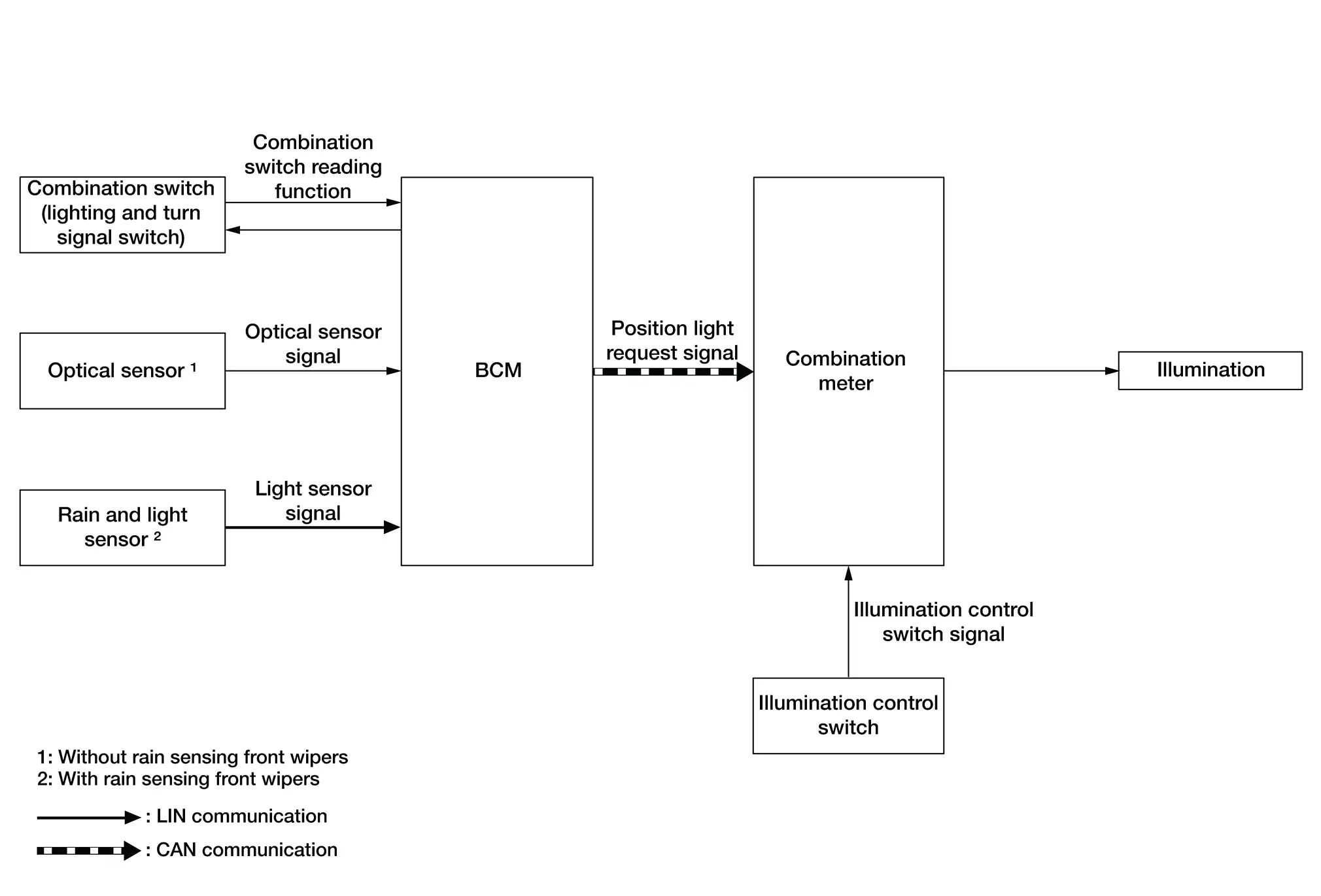
SYSTEM DIAGRAM
| Component | Function |
|---|---|
| Combination switch (lighting and turn signal switch) | Transmits each switch condition signal to the BCM. |
| Optical sensor | Outputs voltage signals to the BCM according to the brightness of ambient light. |
| Rain and light sensor | Transmits the light sensor signal to the BCM via LIN communication. |
| BCM |
|
| Combination meter | Turns illumination ON/OFF according to the request from BCM via CAN communication. |
| Illumination control switch | Transmits the illumination control switch signal the combination meter. |
| Illumination | Combination meter supplies power supply voltage to each illumination, and turns each illumination ON/OFF. |
OUTLINE
Each illumination is controlled by each function of the BCM and combination meter.
Control by BCM
-
Parking, license plate, side marker and tail lamp control function
-
Combination switch reading function
-
Auto light function
Control by combination meter
-
Illumination control function
SIGNAL TRANSMISSION FUNCTION LIST
| Signal name | Input | Output | Description |
|---|---|---|---|
| Combination switch signal | Combination switch (lighting and turn signal switch) | BCM | Transmits the combination switch signal to the BCM. |
| Optical sensor signal | Optical sensor | BCM | Transmits the optical sensor signal to the BCM. |
| Light sensor signal | Rain and light sensor | BCM (LIN) | Transmits the light sensor signal to the BCM. |
| Position light request signal | BCM | Combination meter (CAN) | Transmits the position light request signal via CAN communication. |
| Illumination control switch signal | Illumination control switch | Combination meter | Transmits the illumination control switch signal to the combination meter. |
ILLUMINATION CONTROL
-
Detects each switch condition by the combination switch reading function.
-
BCM transmits the position light request signal to the combination meter according to the tail lamp ON condition. Refer to System Description.
-
Combination meter enters nighttime mode according to the position light request signal and provides power supply to each illumination.
Other materials:
Awd. Periodic Maintenance
Rear Wheel Hub and Housing
Inspection
COMPONENT PARTMake sure that the mounting conditions
(looseness, backlash) of each component and component conditions (wear,
damage) are normal.WHEEL HUB ASSEMBLY (BEARING-INTEGRATED TYPE)Check the following items, and replace the part if necessary.
Mov ...
Basic Inspection. Diagnosis and Repair Work Flow
Work Flow
OVERALL SEQUENCEDETAILED FLOWGET INFORMATION FOR SYMPTOM
Get detailed information from the customer about the symptom (the
condition and the environment when the incident/malfunction occurs).
Check operation condition of the function that is malfunctioning.
>>
G ...
Intelligent Key
CONSULT Function (BCM - INTELLIGENT KEY)
DATA MONITORNOTE:
The following table includes information (items)
inapplicable to this Nissan Ariya vehicle. For information (items)
applicable to this vehicle, refer to CONSULT display items.
Monitor Item Condition
Stop/start switch
[On/Off]
...