Nissan Rogue (T33) 2021-Present Service Manual: System Description :: Component Parts. Tire Pressure Monitoring System
Tire Pressure Monitoring System
Component Parts Location
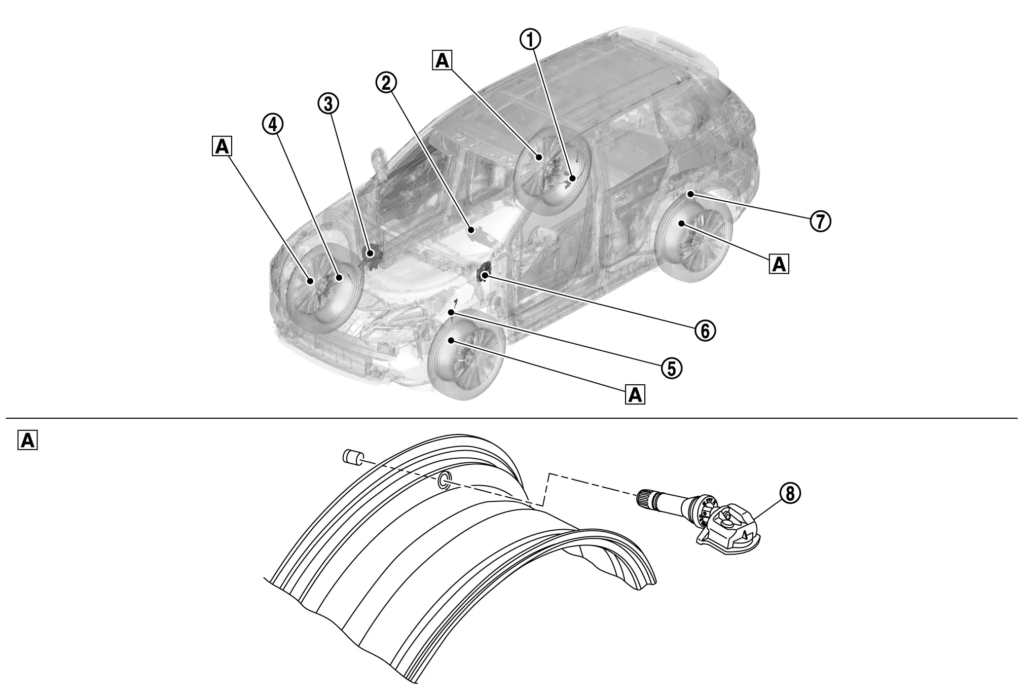
| A. | Wheel (view with wheel and tire removed) | ||||
| No. | Component | Function |
|---|---|---|
| 1. | Rear wheel sensor RH |
Wheel sensor sense the speed of the individual wheel and transmits to the ABS actuator and electric unit (control unit). Refer to Component Parts Location for detailed installation location. |
| 2. | Combination meter | The combination meter receives tire pressure status from the BCM via CAN communication. The combination meter will display the low tire pressure warning lamp when a low tire pressure or system malfunction is detected by the BCM. Refer to Component Parts Location (Type A meter) or Component Parts Location (Type B meter) for detailed installation location. |
| 3. | ABS (Anti-lock Braking System)actuator and electric unit (control unit) |
Mainly transmits the following signal to the BCM via CAN communication:
|
| 4. | Front wheel sensor RH |
Wheel sensor sense the speed of the individual wheel and transmits to the ABS actuator and electric unit (control unit). Refer to Component Parts Location for detailed installation location. |
| 5. | Front wheel sensor LH |
Wheel sensor sense the speed of the individual wheel and transmits to the ABS actuator and electric unit (control unit). Refer to Component Parts Location for detailed installation location. |
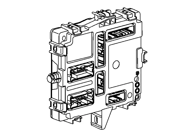
| 6. | BCM (Body Control Module) |
Mainly receives the following signals from the tire pressure sensors:
|
| 7. | Rear wheel sensor LH |
Wheel sensor sense the speed of the individual wheel and transmits to the ABS actuator and electric unit (control unit). Refer to Component Parts Location for detailed installation location. |
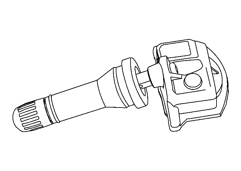
| 8. | Tire pressure sensor | Refer to Tire Pressure Sensor. |
BCM
FUNCTIONS WITHIN THE SYSTEM
-
Tire pressure receiver is integrated in BCM.
-
BCM receives the signals of tire air pressure and tire temperature as an input from the tire pressure sensor in each wheel through a radio signal and controls tire pressure monitoring system.
INDIVIDUAL FUNCTIONS WITHIN THE SYSTEM
BCM uses CAN communication to Illuminate the low tire pressure warning light in the combination meter when tire pressure is lowered to less than the specified value or a system malfunction exists.
INDIVIDUAL OPERATION
Refer to System Description.
PARTS LOCATION
BCM is installed in the LH side of the instrument panel. Refer toComponent Parts Location.
Tire Pressure Sensor
FUNCTIONS WITHIN THE SYSTEM
Tire pressure sensor detects tire air pressure and temperature.
INDIVIDUAL FUNCTIONS WITHIN THE SYSTEM
A tire pressure sensor transmits the detected air pressure and tire temperature in the form of a radio signal to the BCM.
INDIVIDUAL OPERATION
Refer toSystem Description.
PARTS LOCATION
A tire pressure sensor integrated with a valve is install in each wheel. Refer to Component Parts Location.
Other materials:
Security systems
Basic information
Your vehicle includes two types of security systems designed to help protect the Nissan Rogue from unauthorized access:
Vehicle security system (if so equipped)
NISSAN Vehicle Immobilizer System
Vehicle Security System
Basic information
The vehicle security system activates ...
ContrûÇle dynamique
Informations de base
Le contrûÇle dynamique du Nissan Rogue est un module ûˋlectronique avancûˋ regroupant plusieurs fonctions destinûˋes û amûˋliorer la stabilitûˋ, le confort et la tenue de route.
Systû´me de contrûÇle en virage intelligent
ContrûÇle actif de suspension (selon lãûˋquipem ...
How to Use This Manual. Recommended Chemical Products and Sealants
Recommended Chemical Products and Sealants
Refer to the following chart for help in selecting the appropriate chemical product or sealant. Product Description Purpose Nissan North America Part No. (USA) Nissan Canada Part No. (Canada) Aftermarket Cross-reference Part Nos.
1
Rear Vie ...