Nissan Rogue Service Manual: System description
COMPONENT PARTS
Component Parts Location
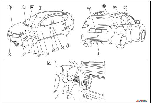
- View right of steering column.
|
No. |
Component |
Function |
| 1 | Combination meter | Combination meter transmits the vehicle speed signal to BCM via CAN
communication. BCM also receives the vehicle speed signal from ABS actuator and electric unit (control unit) via CAN communication. BCM compares both signals to detect the vehicle speed. Security indicator lamp is located on combination meter. Security indicator lamp blinks when ignition switch is in any position other than ON to warn that NISSAN VEHICLE IMMOBILIZER SYSTEM-NATS [NVIS (NATS)] is on board. Refer to MWI-6, "METER SYSTEM : Component Parts Location". |
| 2 | Push-button ignition switch | Push-button ignition switch has push switch inside which detects that push-button ignition switch is pressed, and then transmits ON/OFF signal to BCM. BCM changes the ignition switch position with the operation of push-button ignition switch. BCM maintains the ignition switch position status while push-button ignition switch is not operated. |
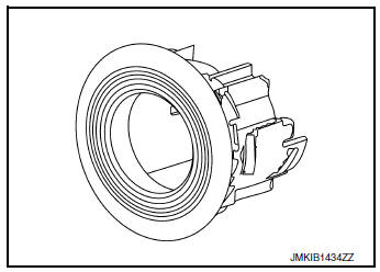
| 3 | NATS antenna amp. | Refer to SEC-8, "NATS Antenna Amp.". |
| 4 | Inside key antenna (instrument center) | Inside key antenna (instrument center) detects whether Intelligent
Key is
inside the vehicle or not, and then transmits the signal to the BCM. Refer to DLK-22, "Inside Key Antenna (Instrument Center)". |
| 5 | Horn | Horn is operated when the panic button on the Intelligent Key is pressed or the alarm is activated. |
| 6 | Hood switch | Hood switch inputs the hood position open/closed to the IPDM E/R. |
| 7 | Transmission range switch | Refer to TM-14, "CVT CONTROL SYSTEM : Transmission Range Switch". |
| 8 | IPDM E/R | Refer to PCS-4, "Component Parts Location". |
| 9 | Stop lamp switch | Refer to BRC-12, "Stop Lamp Switch". |
| 10 | BCM | BCM controls INTELLIGENT KEY SYSTEM (ENGINE START FUNCTION),
NISSAN VEHICLE IMMOBILIZER SYSTEM-NATS [NVIS (NATS)]
and VEHICLE SECURITY SYSTEM. BCM performs the ID verification between BCM and Intelligent Key when the Intelligent Key is carried into the detection area of inside key antenna, and push-button ignition switch is pressed. If the ID verification result is OK, ignition switch operation is available. Then, when the ignition switch is turned ON, BCM performs ID verification between BCM and ECM. If the ID verification result is OK, ECM can start engine. Refer to BCS-7, "BODY CONTROL SYSTEM : Component Parts Location" for detailed installation location. |
| 11 | CVT shift selector | Refer to TM-20, "SHIFT LOCK SYSTEM : Component Parts Location". |
| 12 | Main power window and door lock/unlock switch (Front power window and door lock/ unlock switch RH similar) | Door lock and unlock switch is integrated into the power window main
switch. Door lock and unlock switch transmits door lock/unlock operation signal to BCM. Refer to PWC-7, "Power Window Main Switch". |
| 13 | Outside key antenna LH | Outside key antenna (LH) detects whether Intelligent Key is outside
the
vehicle or not, and then transmits the signal to the BCM. Refer to DLK-23, "Outside Key Antenna (LH)". |
| 14 | Front door lock assembly LH | Door key cylinder switch is integrated into front door lock assembly
(driver
side). Door key cylinder switch detects door LOCK/UNLOCK operation using mechanical key, and then transmits the operation signal to BCM. Refer to DLK-25, "Front Door Lock Assembly (LH)". |
| 15 | Front door switch LH | Door switch detects door open/close condition and then transmits ON/ OFF signal to BCM. |
| 16 | Rear door switch LH (rear door switch RH similar) | Door switch detects door open/close condition and then transmits ON/ OFF signal to BCM. |
| 17 | Outside key antenna RH | Outside key antenna (RH) detects whether Intelligent Key is outside
the
vehicle or not, and then transmits the signal to the BCM. Refer to DLK-23, "Outside Key Antenna (RH)". |
| 18 | Front door switch RH | Door switch detects door open/close condition and then transmits ON/ OFF signal to BCM. |
| 19 | Inside key antenna (console) | Inside key antenna (console) detects whether Intelligent Key is
inside the
vehicle or not, and then transmits the signal to the BCM. Refer to DLK-23, "Inside Key Antenna (Console)". |
| 20 | Back door lock assembly | Back door lock actuator locks/unlocks the back door latch assembly. |
| 21 | Outside key antenna (rear bumper) | Outside key antenna (Rear bumper) detects whether Intelligent Key is
outside
the vehicle or not, and then transmits the signal to the BCM. Refer to DLK-23, "Outside Key Antenna (Rear Bumper)". |
NATS Antenna Amp.
The ID verification is performed between BCM and transponder integrated into Intelligent Key via NATS antenna amp. when Intelligent Key backside is contacted to push-button ignition switch in case that Intelligent Key battery is discharged. If the ID verification result is OK, the operation of ignition switch is available.
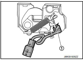
Hood Switch
Hood switch 1 detects that hood is open, and then transmits ON/ OFF signal to IPDM E/R. IPDM E/R transmits hood switch signal to BCM via CAN communication. Hood switch is integrated into hood lock assembly LH.
SYSTEM
INTELLIGENT KEY SYSTEM/ENGINE START FUNCTION
INTELLIGENT KEY SYSTEM/ENGINE START FUNCTION : System Diagram
INTELLIGENT KEY SYSTEM/ENGINE START FUNCTION : System Des
SYSTEM DESCRIPTION
- The engine start function of Intelligent Key system makes it
possible to start and stop the engine without
using the key, based on the electronic ID verification. The electronic ID
verification is performed between
BCM and Intelligent Key when the push-button ignition switch is pressed
while the Intelligent Key is within
the detection area of inside key antenna.
NOTE: The driver should carry the Intelligent Key at all times.
- Intelligent Key has 2 IDs [Intelligent Key ID and NVIS (NATS) ID]. It can perform the door lock/unlock operation and the push-button ignition switch operation when the registered Intelligent Key is carried.
- When Intelligent Key battery is discharged, engine can be started by operating push-button ignition switch after contacting Intelligent Key backside to push-button ignition switch. At that time, the NVIS (NATS) ID verification is performed.
- If the ID is successfully verified, when push-button ignition switch is pressed, the engine can be started.
- Up to 4 Intelligent Keys can be registered (Including the standard Intelligent Key) upon request from the customer.
NOTE: Refer to SEC-12, "NISSAN VEHICLE IMMOBILIZER SYSTEM-NATS : System Description" for any functions other than engine start function of Intelligent Key system.
PRECAUTIONS FOR INTELLIGENT KEY SYSTEM
The transponder [the chip for NVIS (NATS) ID verification] is integrated into the Intelligent Key.
In that case, the NVIS (NATS) ID verification can be performed when Intelligent Key backside is contacted to push-button ignition switch. If verification result is OK, engine can be started.
OPERATION WHEN INTELLIGENT KEY IS CARRIED
- When the push-button ignition switch is pressed, the BCM activates the inside key antenna and transmits the request signal to the Intelligent Key.
- The Intelligent Key receives the request signal and transmits the Intelligent Key ID signal to the BCM.
- BCM receives the Intelligent Key ID signal and verifies it with the registered ID.
- BCM turns ACC relay ON and transmits the ignition power supply ON signal to IPDM E/R.
- IPDM E/R turns the ignition relay ON and starts the ignition power supply.
- BCM detects that the selector lever position and brake pedal operating condition.
- BCM transmits the starter request signal to IPDM E/R and turns the starter relay in IPDM E/R ON if BCM judges that the engine start condition* is satisfied.
- IPDM E/R turns the starter control relay ON when receiving the starter request signal.
- Power supply is supplied through the starter relay and the starter
control relay to operate the starter motor.
CAUTION: If a malfunction is detected in the Intelligent Key system, the “KEY” warning lamp in the combination meter illuminates. At that time, the engine cannot be started.
- When BCM receives feedback signal from ECM indicating that the engine is started, the BCM transmits a stop signal to IPDM E/R and stops cranking by turning OFF the starter motor relay. (If engine start is unsuccessful, cranking stops automatically within 5 seconds.)
CAUTION: When the Intelligent Key is carried outside of the vehicle (inside key antenna detection area) while the power supply is in the ACC or ON position, even if the engine start condition* is satisfied, the engine cannot be started.
*: For the engine start condition, refer to the table below “POWER SUPPLY POSITION CHANGE TABLE BY PUSH-BUTTON IGNITION SWITCH OPERATION”.
OPERATION RANGE
Engine can be started when Intelligent Key is inside the vehicle. However, sometimes engine may not start when Intelligent Key is on instrument panel or in glove box.
ENGINE START OPERATION WHEN INTELLIGENT KEY IS CONTACTED TO PUSH-BUTTON IGNITION SWITCH
When Intelligent Key battery is discharged, the NVIS (NATS) ID verification between transponder in Intelligent Key and BCM is performed when Intelligent Key backside is contacted to push-button ignition switch. If the verification result is OK, engine can be started.
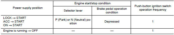
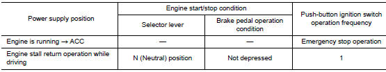
POWER SUPPLY POSITION CHANGE TABLE BY PUSH-BUTTON IGNITION SWITCH OPERATION
The power supply position changing operation can be performed with the following operations.
NOTE:
- When an Intelligent Key is within the detection area of inside key antenna and when Intelligent Key backside is contacted to push-button ignition switch, it is equivalent to the operations below.
- When starting the engine, the BCM monitors under the engine start conditions:
- Brake pedal operating condition
- Selector lever position
- Vehicle speed
Vehicle speed: less than 4 km/h (2.5 MPH)
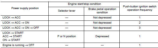
Vehicle speed: 4 km/h (2.5 MPH) or more
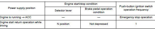
Emergency stop operation
- Press and hold the push-button ignition switch for 2 seconds or more.
- Press the push-button ignition switch 3 times or more within 1.5 seconds.
NISSAN VEHICLE IMMOBILIZER SYSTEM-NATS
NISSAN VEHICLE IMMOBILIZER SYSTEM-NATS : System Diagram
NISSAN VEHICLE IMMOBILIZER SYSTEM-NATS : System Description
SYSTEM DESCRIPTION
- The NISSAN VEHICLE IMMOBILIZER SYSTEM-NATS [NVIS (NATS)] prevents the engine from being started by Intelligent Key whose ID is not registered to the vehicle (BCM). It has higher protection against auto theft involving the duplication of mechanical keys.
- The ignition key integrated in the Intelligent Key cannot start the engine. When the Intelligent Key battery is discharged, the NVIS (NATS) ID verification is performed between the transponder integrated with Intelligent Key and BCM via NATS antenna amp. when the Intelligent Key backside is contacted to push-button ignition switch. If the verification results are OK, the engine start operation can be performed by the push-button ignition switch operation.
- Locate the security indicator lamp and apply the anti-theft system equipment sticker that warns that the NVIS (NATS) is on-board the model.
- Security indicator lamp always blinks when the power supply position is any position other than ON.
- Up to 4 Intelligent Keys can be registered (including the standard ignition key) upon request from the owner.
- Specified registration is required when replacing ECM, BCM or Intelligent Key.
- Possible symptom of NVIS (NATS) malfunction is “Engine cannot start”. The engine can not be started because of other than NVIS (NATS) malfunction, so start the trouble diagnosis according to SEC-62, "Work Flow".
- If ECM other than genuine part is installed, the engine cannot be started. For ECM replacement procedure, refer to EC-499, "Removal and Installation".
PRECAUTIONS FOR KEY REGISTRATION
- The ID registration is a procedure that erases the current NVIS (NATS) ID once, and then reregisters a new ID. Therefore before starting the registration operation, collect all registered Intelligent Keys from the customer.
- When registering the Intelligent Key, perform only one procedure to simultaneously register both ID [NVIS (NATS) ID and Intelligent Key ID].
SECURITY INDICATOR LAMP
- Warns that the vehicle is equipped with NVIS (NATS)
- Security indicator lamp always blinks when the power supply position is any position other than ON.
NOTE: Because security indicator lamp is highly efficient, the battery is barely affected.
ENGINE START OPERATION WHEN INTELLIGENT KEY IS CONTACTED TO PUSH-BUTTON IGNITION SWITCH
- When brake pedal is depressed while selector lever is in the P (Park) position, BCM activates NATS antenna amp. that is located behind push-button ignition switch.
- When Intelligent Key (transponder built-in) backside is contacted to push-button ignition switch, BCM starts NVIS (NATS) ID verification between BCM and Intelligent Key (transponder built-in) via NATS antenna amp.
- When the NVIS (NATS) ID verification result is OK, buzzer in combination meter sounds and BCM transmits the result to ECM.
- BCM turns ACC relay ON and transmits ignition power supply ON signal to IPDM E/R.
- IPDM E/R turns the ignition relay ON and starts the ignition power supply.
- BCM detects that the selector lever position is P (Park) or N (Neutral).
- BCM transmits starter request signal to IPDM E/R and turns the starter relay in IPDM E/R ON if BCM judges that the engine start condition* is satisfied.
- IPDM E/R turns the starter control relay ON when receiving the starter request signal.
- Power supply is supplied through the starter relay and the starter control relay to operate the starter motor.
- . When BCM receives feedback signal from ECM indicating that the engine is started, BCM transmits a stop signal to IPDM E/R and stops cranking by turning off the starter motor relay. (If engine start is unsuccessful, cranking stops automatically within 5 seconds.)
*: For the engine start condition, refer to the table “POWER SUPPLY POSITION CHANGE TABLE BY PUSHBUTTON IGNITION SWITCH OPERATION” below.
POWER SUPPLY POSITION CHANGE TABLE BY PUSH-BUTTON IGNITION SWITCH OPERATION
The power supply position changing operation can be performed with the following operations.
NOTE:
- When an Intelligent Key is within the detection area of inside key antenna and when Intelligent Key backside is contacted to push-button ignition switch, it is equivalent to the operations below.
- When starting the engine, the BCM monitors under the engine start conditions:
- Brake pedal operating condition
- Selector lever position
- Vehicle speed
Vehicle speed: less than 4 km/h (2.5 MPH)
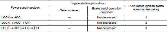
Vehicle speed: 4 km/h (2.5 MPH) or more
Emergency stop operation
- Press and hold the push-button ignition switch for 2 seconds or more.
- Press the push-button ignition switch 3 times or more within 1.5 seconds.
VEHICLE SECURITY SYSTEM
VEHICLE SECURITY SYSTEM : System Diagram
VEHICLE SECURITY SYSTEM : System Description
- The vehicle security system has two alarm functions (theft warning alarm and panic alarm) and reduces the possibility of a theft or mischief by activating horns and headlamps intermittently.
- The panic alarm does not start when the theft warning alarm is
activating and the panic alarm stops when
the theft warning alarm is activated.
The priority of the functions are as per the following.

THEFT WARNING ALARM
- The theft warning alarm function activates horns and headlamps intermittently when BCM detects that any door or hood is opened by unauthorized means while the system is in the ARMED state.
- Security indicator lamp on combination meter always blinks when power supply position is any position other than ON. Security indicator lamp blinking warns that the vehicle is equipped with a vehicle security system.
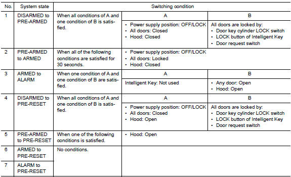
Operation Flow
NOTE:
- BCM ignores the door key cylinder UNLOCK switch signal input for 1 second after the door key cylinder LOCK switch signal input.
- To lock/unlock all doors by operating remote controller button of Intelligent Key or door request switch, Intelligent Key must be within the detection area of outside key antenna. For details, refer to SEC-9, "INTELLIGENT KEY SYSTEM/ENGINE START FUNCTION : System Description".
- To open back door by operating back door opener switch, Intelligent Key must be within the detection area of outside key antenna. For details, refer to SEC-9, "INTELLIGENT KEY SYSTEM/ENGINE START FUNCTION : System Description".
DISARMED Phase
The vehicle security system is not set in the DISARMED phase. The vehicle security system stays in this phase while any door is open because it is assumed that the owner is inside or nearby the vehicle. Security indicator lamp blinks every 2.4 seconds.
When the vehicle security system is reset, each phase switches to the DISARMED phase directly.
PRE-ARMED Phase
The PRE-ARMED phase is the transient state between the DISARMED phase and the ARMED phase. This phase is maintained for 30 seconds so that the owner can reset the setting due to a mis-operation. This phase switches to the ARMED phase when vehicle conditions are not changed for 30 seconds. Security indicator lamp illuminates while being in this phase.
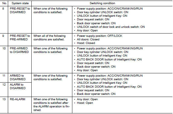
To reset the PRE-ARMED phase, refer to the switching condition of No. 10 in the table above
ARMED Phase
The vehicle security system is set and BCM monitors all necessary inputs. If any door or hood is opened without using Intelligent Key, vehicle security system switches to the ALARM phase. Security indicator lamp blinks every 2.4 seconds.
To reset the ARMED phase, refer to the switching condition of No. 11 in the table above.
ALARM Phase
BCM transmits “Theft Warning Horn Request” signal and “High Beam Request” signal intermittently to IPDM E/R via CAN communication. In this phase, horns and headlamps are activated intermittently for approximately 50 seconds to warn that the vehicle is accessed by unauthorized means. ON/OFF timing of horns and headlamps are synchronized. After 50 seconds, the vehicle security system returns to the ARMED phase. At this time, if BCM still detects unauthorized access to the vehicle, the system is switched to the ALARM phase again. This RE-ALARM operation is carried out a maximum of 2 times.
To cancel the ALARM operation, refer to the switching condition of No. 12 in the table above.
NOTE: If a battery terminal is disconnected during the ALARM phase, theft warning alarm stops. But when the battery terminal is reconnected, theft warning alarm is activated again.
PRE-RESET Phase
The PRE-RESET phase is the transient state between each phase and DISARMED phase. If only the condition of hood is not satisfied, the system switches to the PRE-RESET phase. Then, when any condition is changed, the system switches to the DISARMED phase or PRE-ARMED phase.
PANIC ALARM
- The panic alarm function activates horns and headlamps intermittently when the owner presses the PANIC ALARM button of Intelligent Key outside the vehicle while the power supply position is OFF or LOCK.
- When BCM receives panic alarm signal from Intelligent Key, BCM transmits “Theft Warning Horn Request” signal and “High Beam Request” signal intermittently to IPDM E/R via CAN communication. To prevent the activation due to mis-operation of Intelligent Key by owner, the panic alarm function is activated when BCM receives the signal for 0.4 - 0.6 seconds.
- Panic alarm operation is maintained for 25 seconds.
- Panic alarm operation is cancelled when BCM receives one of the following signals:
- LOCK button of Intelligent Key: ON
- UNLOCK button of Intelligent Key: ON
- PANIC ALARM button of Intelligent Key: Long pressed
- Any door request switch: ON
DIAGNOSIS SYSTEM (BCM)
COMMON ITEM
COMMON ITEM : CONSULT Function (BCM - COMMON ITEM)
APPLICATION ITEM
CONSULT performs the following functions via CAN communication with BCM.
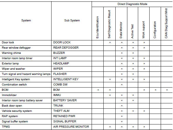
SYSTEM APPLICATION
BCM can perform the following functions.
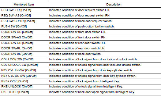
INTELLIGENT KEY
INTELLIGENT KEY : CONSULT Function (BCM - INTELLIGENT KEY)
SELF DIAGNOSTIC RESULT
Refer to BCS-48, "DTC Index".
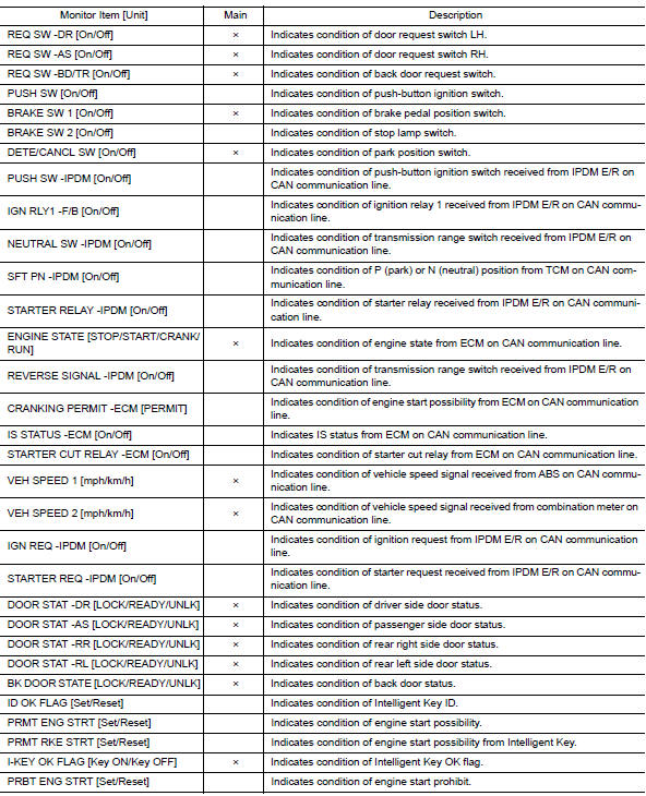
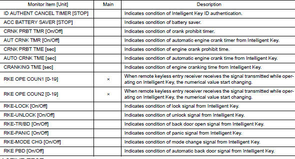
DATA MONITOR
ACTIVE TEST
WORK SUPPORT
IMMU
IMMU : CONSULT Function (BCM - IMMU)
SELF DIAGNOSTIC RESULT
Refer to BCS-48, "DTC Index".
DATA MONITOR

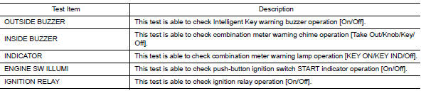
ACTIVE TEST

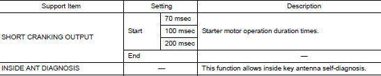
WORK SUPPORT

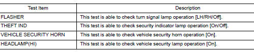
THEFT ALM
THEFT ALM : CONSULT Function (BCM - THEFT ALM)
DATA MONITOR
ACTIVE TEST
WORK SUPPORT

DIAGNOSIS SYSTEM (IPDM E/R)
CONSULT Function (IPDM E/R)
APPLICATION ITEM
CONSULT performs the following functions via CAN communication with IPDM E/R.
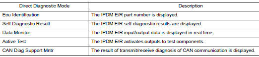
ECU IDENTIFICATION
The IPDM E/R part number is displayed.
SELF DIAGNOSTIC RESULT
Refer to PCS-20, "DTC Index".
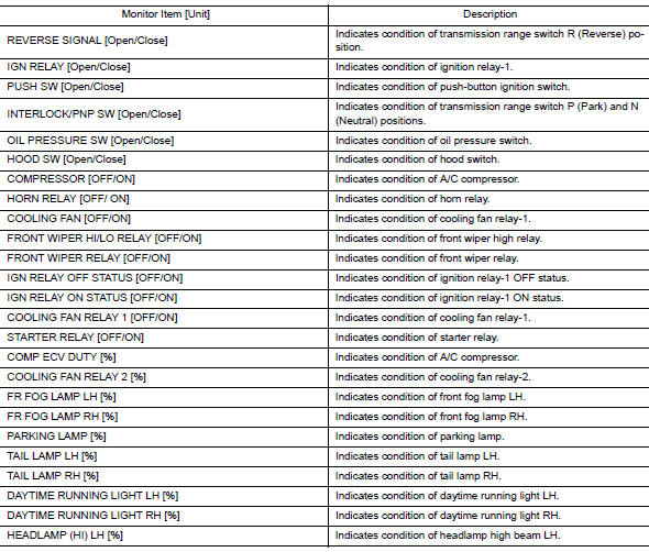
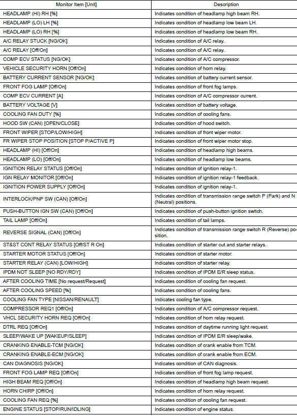
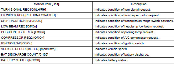
DATA MONITOR
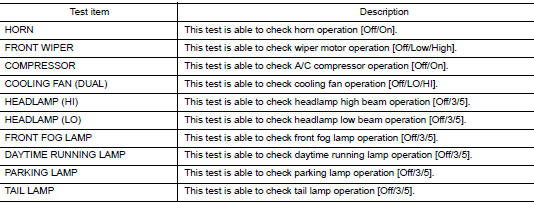
ACTIVE TEST
CAN DIAG SUPPORT MNTR
Refer to LAN-14, "CAN Diagnostic Support Monitor".
 Precaution
Precaution for Supplemental Restraint System (SRS) "AIR BAG" and "SEAT
BELT
PRE-TENSIONER"
The Supplemental Restraint System such as “AIR BAG” and “SEAT BELT PRE-TENSIONE ...
 ECU diagnosis information
ECM, IPDM E/R, BCM
List of ECU Reference
...
Other materials:
Symptom diagnosi
NOISE, VIBRATION, AND HARSHNESS (NVH) TROUBLESHOOTING
NVH troubleshooting - engine noise
Valve mechanism
Intake and exhaust valve
Water pump
Timing chain
Drive belt
Rotation mechanism
Tappet noise
Camshaft bearing noise
&nb ...
Securing the load
Cargo area luggage hooks
There are luggage hooks located in the cargo
area as shown. The hooks can be used to secure
cargo with ropes or other types of straps.
Do not apply a total load of more than
6.5 lbs. (29 N) to a single metal floor hook
when securing cargo.
WARNING
&nb ...
Diagnosis system (BCM) (with intelligent key system)
COMMON ITEM
COMMON ITEM : CONSULT Function (BCM - COMMON ITEM)
APPLICATION ITEM
CONSULT performs the following functions via CAN communication with BCM.
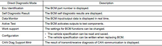
Direct Diagnostic Mode
Description
Ecu Identification
The BCM part number is displayed.
Self Diagnostic ...
