Nissan Rogue Service Manual: ECU diagnosis information
ECM, IPDM E/R, BCM
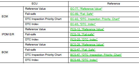
List of ECU Reference
 System description
COMPONENT PARTS
Component Parts Location
View right of steering column.
No.
Component
Function
1
Combination meter
Combination meter transmits the v ...
 Wiring diagram
ENGINE START FUNCTION
Wiring Diagram
NISSAN VEHICLE IMMOBILIZER SYSTEM-NATS
Wiring Diagram
VEHICLE SECUR ...
Other materials:
U1000 CAN COMM circuit
Description
CAN (Controller Area Network) is a serial communication line for real-time
application. It is an on-vehicle multiplex
communication line with high data communication speed and excellent malfunction
detection ability.
Many electronic control units are equipped onto a vehicle, and ...
U1000 CAN COMM circuit
Description
CAN (Controller Area Network) is a serial communication line for real time
application. It is an on-vehicle multiplex
communication line with high data communication speed and excellent error
detection ability. Many electronic
control units are equipped onto a vehicle, and each co ...
EPS warning lamp
Component Function Check
1.CHECK THE ILLUMINATION OF THE EPS WARNING LAMP
Check that the EPS warning lamp turns ON when ignition switch turns ON. Then,
EPS warning lamp turns
OFF after the engine is started.
Is the inspection result normal?
YES >> Inspection End.
NO >> Perfor ...
