Nissan Rogue Service Manual: System
System Diagram
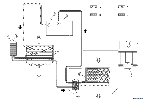
- Compressor
- Pressure relief valve
- Liquid tank
- Refrigerant pressure sensor
- Condenser
- Expansion valve
- Evaporator
- Blower motor
- High-pressure gas
- High-pressure liquid
- Low-pressure liquid
- Low-pressure gas
- Suction port
- Discharge port
- Outside air
System Description
REFRIGERANT CYCLE
Refrigerant Flow
The refrigerant from the compressor flows through the condenser and liquid tank, evaporator, and returns to the compressor. The refrigerant evaporation in the evaporator is controlled by an expansion valve.
Freeze Protection
To prevent evaporator from freezing up, the evaporator air temperature is monitored and the voltage signal to the A/C auto amp. makes the A/C relay go OFF and stop the compressor.
REFRIGERANT SYSTEM PROTECTION
Refrigerant Pressure Sensor
- The refrigerant system is protected against excessively high or low pressures by the refrigerant pressure sensor, located on the liquid tank. The refrigerant pressure sensor detects the pressure inside the refrigerant line and sends the voltage signal to the ECM if the system pressure rises above or falls below the specifications.
- ECM turns the A/C relay to OFF and stops the compressor when the high-pressure side detected by refrigerant pressure sensor to have the following conditions:
- Approximately 3,120 kPa (31.8 kg/cm2, 452 psi) or more (Engine speed is 1,500 rpm or more.)
- Approximately 2,740 kPa (27.9 kg/cm2, 397 psi) or more (Engine speed is less than 1,500 rpm.)
- Approximately 120 kPa (1.2 kg/cm2, 17 psi) or less
Pressure Relief Valve
The refrigerant system is also protected by a pressure relief valve, located in the rear head of the compressor.
The release port on the pressure relief valve automatically opens and releases refrigerant into the atmosphere when the pressure of refrigerant in the system increases to an unusual level [more than 3,800 kPa (38.8 kg/ cm2, 551 psi)].
 Component parts
Component Parts Location
Condenser
Compressor
Refrigerant pressure sensor
Liquid tank
Expansion valve
Evaporator
Component Description
Component
Description ...
 Basic inspection
DIAGNOSIS AND REPAIR WORKFLOW
Workflow
OVERALL SEQUENCE
DETAILED FLOW
1.INTERVIEW CUSTOMER
Interview the customer to obtain as much information as possible about the
conditions and environm ...
Other materials:
Symptom diagnosis
EXTERIOR LIGHTING SYSTEM SYMPTOMS
Symptom Table
CAUTION:
Perform the self-diagnosis with CONSULT before the symptom diagnosis. Perform
the trouble diagnosis
if any DTC is detected.
NORMAL OPERATING CONDITION
Description
AUTO LIGHT SYSTEM
The headlamp may not be turned ON/OFF immedi ...
Basic inspection
DIAGNOSIS AND REPAIR WORKFLOW
Work Flow
OVERALL SEQUENCE
DETAILED FLOW
1.GET INFORMATION FOR SYMPTOM
Get detailed information from the customer about the symptom (the
condition and the environment when
the incident/malfunction occurs).
Check operation condition of the ...
Throttle valve closed position learning
Description
Throttle Valve Closed Position Learning is a function of ECM to learn the
fully closed position of the throttle
valve by monitoring the throttle position sensor output signal. It must be
performed each time the harness connector
of the electric throttle control actuator or ECM is ...
