Nissan Rogue Service Manual: Basic inspection
DIAGNOSIS AND REPAIR WORKFLOW
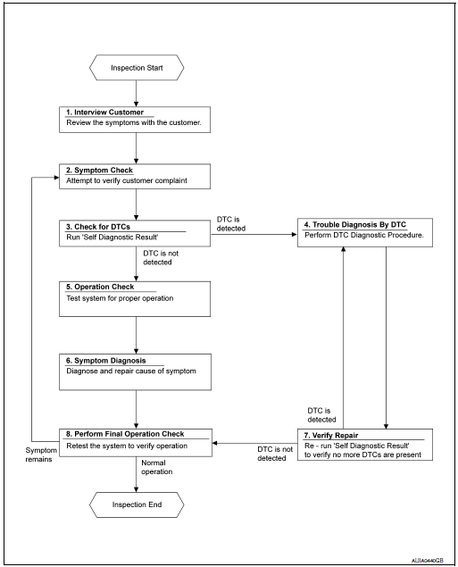
Workflow
OVERALL SEQUENCE

DETAILED FLOW
1.INTERVIEW CUSTOMER
Interview the customer to obtain as much information as possible about the conditions and environment under which the malfunction occurred.
>> GO TO 2.
2.SYMPTOM CHECK
Verify symptoms.
>> GO TO 3.
3.CHECK FOR DTCS
 With CONSULT
- Turn ignition switch ON.
- Select “Self Diagnostic Result” mode of “HVAC” using CONSULT.
- Check DTC.
Is any DTC detected? YES >> GO TO 4.
NO >> GO TO 5.
4.PERFORM DTC DIAGNOSTIC PROCEDURE
Perform the diagnostic procedure for the detected DTC. Refer to HAC-32, "DTC Inspection Priority Chart" (automatic A/C) or HAC-134, "DTC Inspection Priority Chart" (manual A/C).
>> GO TO 7.
5.OPERATION CHECK
Perform the operation check. Refer to HAC-48, "Work Procedure" (automatic A/C) or HAC-148, "Work Procedure" (manual A/C).
>> GO TO 6.
6.SYMPTOM DIAGNOSIS
Check the symptom diagnosis table. Refer to HAC-96, "Diagnosis Chart By Symptom" (automatic A/C) or HAC-174, "Symptom Table" (manual A/C).
>> GO TO 8.
7.VERIFY REPAIR.
 With CONSULT
- Turn ignition switch ON.
- Select “Self Diagnostic Result” mode of “HVAC” using CONSULT.
- Check DTC.
Is any DTC detected? YES >> GO TO 4.
NO >> GO TO 8.
8.PERFORM FINAL OPERATION CHECK
Perform the operation check. Refer to HAC-48, "Work Procedure" (automatic A/C) or HAC-148, "Work Procedure" (manual A/C).
Does it operate normally? YES >> Inspection End.
NO >> GO TO 2.
 System
System Diagram
Compressor
Pressure relief valve
Liquid tank
Refrigerant pressure sensor
Condenser
Expansion valve
Evaporator
Blower motor
High-pressure gas
&n ...
Other materials:
C1170 variant coding
DTC Logic
DTC DETECTION LOGIC
DTC
Display Item
Malfunction detected condition
Possible causes
C1170
VARIANT CODING
When the information in ABS actuator and electric
unit (control unit) is not the same.
ABS actuator and electric unit
(control unit)
DTC ...
Brake pedal
Adjustment
BRAKE PEDAL HEIGHT
Remove instrument lower panel LH. Refer to IP-22, "Removal and
Installation".
Disconnect the harness connectors from the stop lamp switch and
brake pedal position switch.
Turn the stop lamp switch and brake pedal position switc ...
CAN system (type 1)
DTC/CIRCUIT DIAGNOSIS
MAIN LINE BETWEEN IPDM-E AND DLC CIRCUIT
Diagnosis Procedure
1.CHECK CONNECTOR
Turn the ignition switch OFF.
Disconnect the battery cable from the negative terminal.
Check the following terminals and connectors for damage, bend and
loose connecti ...

