Nissan Rogue Service Manual: System
ENGINE CONTROL SYSTEM
ENGINE CONTROL SYSTEM : System Description
SYSTEM DIAGRAM
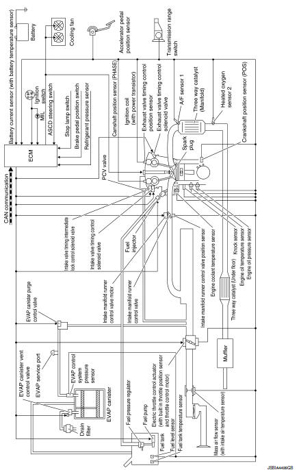
SYSTEM DESCRIPTION
ECM controls the engine by various functions.
| Function | Reference |
| Multiport fuel injection system | EC-34, "MULTIPORT FUEL INJECTION SYSTEM : System Description (with automatic air conditioner)" |
| Electric ignition system | EC-39, "ELECTRIC IGNITION SYSTEM : System Description" |
| Intake valve timing control | EC-40, "INTAKE VALVE TIMING CONTROL : System Description" |
| Exhaust valve timing control | EC-43, "EXHAUST VALVE TIMING CONTROL : System Description" |
| Intake manifold runner control | EC-44, "INTAKE MANIFOLD RUNNER CONTROL : System Description |
| Engine protection control | EC-44, "ENGINE PROTECTION CONTROL AT LOW ENGINE OIL PRESSURE : System Description" |
| Fuel filler cap warning system | EC-48, "FUEL FILLER CAP WARNING SYSTEM : System Description" |
| Air conditioning cut control | EC-45, "AIR CONDITIONING CUT CONTROL : System Description" |
| Power generation voltage variable control | EC-45, "POWER GENERATION VOLTAGE VARIABLE CONTROL SYSTEM : System Description" |
| Cooling fan control | EC-46, "COOLING FAN CONTROL : System Description" |
| Evaporative emission system | EC-53, "EVAPORATIVE EMISSION SYSTEM : System Description" |
| Automatic speed control device (ASCD) | EC-47, "AUTOMATIC SPEED CONTROL DEVICE (ASCD) : System Description" |
| CAN communication | EC-53, "CAN COMMUNICATION : System Description" |
| Sport mode | EC-54, "SPORT MODE CONTROL : System Description" |
ENGINE CONTROL SYSTEM : Fail Safe
NON DTC RELATED ITEM
| Detected items | Engine operating condition in fail-safe mode | Remarks |
| Malfunction indicator lamp circuit | Engine speed will not rise more than 2,500 rpm due to the fuel cut | When there is an open circuit on MIL circuit, the ECM cannot warn
the
driver by lighting up MIL when there is malfunction on engine control
system.
Therefore, when electrical controlled throttle and part of ECM related diagnoses are continuously detected as NG for 5 trips, ECM warns the driver that engine control system malfunctions and MIL circuit is open by means of operating fail safe function. The fail safe function also operates when above diagnoses except MIL circuit are detected and demands the driver to repair the malfunction. |
DTC RELATED ITEM
Description
When a DTC is detected, ECM executes a mode (in the Fail-safe mode) applicable to the DTC. The fail-safe mode has the preset traveling control mode (accelerator angle variation and engine output limit) and device fix mode.
| Fail safe mode | Vehicle behavior | |
| Traveling control mode | Accelerator angle variation control | ECM controls the accelerator pedal depression speed to
make it slower than actual speed. This
causes a drop in accelerating performance and encourages the driver to
repair malfunction.
NOTE: ECM does not control the accelerator pedal releasing speed. |
| Engine output control | ECM reduces the engine output, according to the rise in engine speed. This reduces the vehicle speed to encourage the driver to repair malfunction. | |
| Device fix mode |
|
|
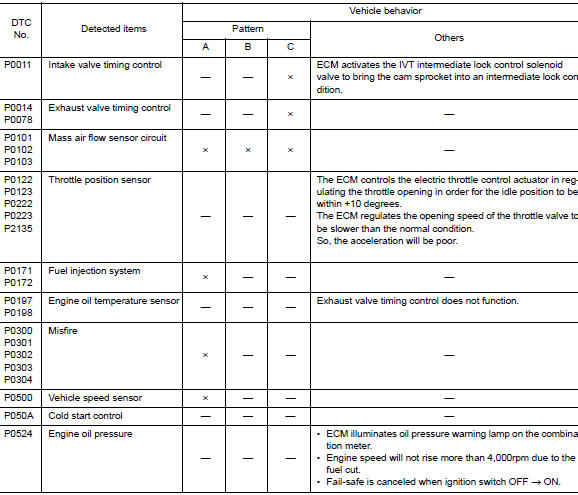
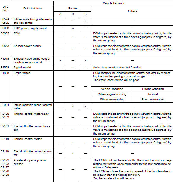
Fail Safe Pattern
| Pattern | Fail safe mode | |
| A | Traveling control mode | Accelerator angle variation control |
| B | Engine output control | |
| C | Device fix mode | |
Fail Safe List
Ч:Applicable —: Not applicable
MULTIPORT FUEL INJECTION SYSTEM
MULTIPORT FUEL INJECTION SYSTEM : System Description (with automatic air conditioner)
SYSTEM DIAGRAM
SYSTEM DESCRIPTION
The amount of fuel injected from the fuel injector is determined by the ECM. The ECM controls the length of time the valve remains open (injection pulse duration). The amount of fuel injected is a program value in the ECM memory. The program value is preset by engine operating conditions. These conditions are determined by input signals (for engine speed and intake air) from the crankshaft position sensor (POS), camshaft position sensor (PHASE) and the mass air flow sensor.
VARIOUS FUEL INJECTION INCREASE/DECREASE COMPENSATION
In addition, the amount of fuel injected is compensated to improve engine performance under various operating conditions as listed below.
<Fuel increase>
- During warm-up
- When starting the engine
- During acceleration
- Hot-engine operation
- When selector lever is changed from N to D
- High-load, high-speed operation
<Fuel decrease>
- During deceleration
- During high engine speed operation
MIXTURE RATIO FEEDBACK CONTROL (CLOSED LOOP CONTROL)
The mixture ratio feedback system provides the best air-fuel mixture ratio for driveability and emission control.
The three way catalyst (manifold) can then better reduce CO, HC and NOx emissions. This system uses A/F sensor 1 in the exhaust manifold to monitor whether the engine operation is rich or lean. The ECM adjusts the injection pulse width according to the sensor voltage signal. For more information about A/F sensor 1, refer to EC-24, "Air Fuel Ratio (A/F) Sensor 1". This maintains the mixture ratio within the range of stoichiometric (ideal air-fuel mixture).
This stage is referred to as the closed loop control condition.
Heated oxygen sensor 2 is located downstream of the three way catalyst (manifold). Even if the switching characteristics of A/F sensor 1 shift, the air-fuel ratio is controlled to stoichiometric by the signal from heated oxygen sensor 2.
- Open Loop Control
The open loop system condition refers to when the ECM detects any of the following conditions. Feedback control stops in order to maintain stabilized fuel combustion.
- Deceleration and acceleration
- High-load, high-speed operation
- Malfunction of A/F sensor 1 or its circuit
- Insufficient activation of A/F sensor 1 at low engine coolant temperature
- High engine coolant temperature
- During warm-up
- After shifting from N to D
- When starting the engine
MIXTURE RATIO SELF-LEARNING CONTROL
The mixture ratio feedback control system monitors the mixture ratio signal transmitted from A/F sensor 1.
This feedback signal is then sent to the ECM. The ECM controls the basic mixture ratio as close to the theoretical mixture ratio as possible. However, the basic mixture ratio is not necessarily controlled as originally designed. Both manufacturing differences (i.e., mass air flow sensor hot wire) and characteristic changes during operation (i.e., fuel injector clogging) directly affect mixture ratio.
Accordingly, the difference between the basic and theoretical mixture ratios is monitored in this system. This is then computed in terms of “injection pulse duration” to automatically compensate for the difference between the two ratios.
“Fuel trim” refers to the feedback compensation value compared against the basic injection duration. Fuel trim includes short term fuel trim and long term fuel trim.
“Short term fuel trim” is the short-term fuel compensation used to maintain the mixture ratio at its theoretical value. The signal from A/F sensor 1 indicates whether the mixture ratio is RICH or LEAN compared to the theoretical value. The signal then triggers a reduction in fuel volume if the mixture ratio is rich, and an increase in fuel volume if it is lean.
“Long term fuel trim” is overall fuel compensation carried out long-term to compensate for continual deviation of the short term fuel trim from the central value. Such deviation will occur due to individual engine differences, wear over time and changes in the usage environment.
FUEL INJECTION TIMING
Two types of systems are used.
- Sequential Multiport Fuel Injection System
Fuel is injected into each cylinder during each engine cycle according to the firing order. This system is used when the engine is running. - Simultaneous Multiport Fuel Injection System
Fuel is injected simultaneously into all four cylinders twice each engine cycle. In other words, pulse signals of the same width are simultaneously transmitted from the ECM.The four injectors will then receive the signals two times for each engine cycle.
This system is used when the engine is being started and/or if the fail-safe system (CPU) is operating.
FUEL SHUT-OFF
Fuel to each cylinder is cut off during deceleration, operation of the engine at excessively high speeds or operation of the vehicle at excessively high speeds.
MULTIPORT FUEL INJECTION SYSTEM : System Description (with manual air conditioner)
SYSTEM DIAGRAM
SYSTEM DESCRIPTION
The amount of fuel injected from the fuel injector is determined by the ECM. The ECM controls the length of time the valve remains open (injection pulse duration). The amount of fuel injected is a program value in the ECM memory. The program value is preset by engine operating conditions. These conditions are determined by input signals (for engine speed and intake air) from the crankshaft position sensor (POS), camshaft position sensor (PHASE) and the mass air flow sensor.
VARIOUS FUEL INJECTION INCREASE/DECREASE COMPENSATION
In addition, the amount of fuel injected is compensated to improve engine performance under various operating conditions as listed below.
<Fuel increase>
- During warm-up
- When starting the engine
- During acceleration
- Hot-engine operation
- When selector lever is changed from N to D
- High-load, high-speed operation
<Fuel decrease>
- During deceleration
- During high engine speed operation
MIXTURE RATIO FEEDBACK CONTROL (CLOSED LOOP CONTROL)

The mixture ratio feedback system provides the best air-fuel mixture ratio for driveability and emission control.
The three way catalyst (manifold) can then better reduce CO, HC and NOx emissions. This system uses A/F sensor 1 in the exhaust manifold to monitor whether the engine operation is rich or lean. The ECM adjusts the injection pulse width according to the sensor voltage signal. For more information about A/F sensor 1, refer to EC-24, "Air Fuel Ratio (A/F) Sensor 1". This maintains the mixture ratio within the range of stoichiometric (ideal air-fuel mixture).
This stage is referred to as the closed loop control condition.
Heated oxygen sensor 2 is located downstream of the three way catalyst (manifold). Even if the switching characteristics of A/F sensor 1 shift, the air-fuel ratio is controlled to stoichiometric by the signal from heated oxygen sensor 2.
- Open Loop Control
The open loop system condition refers to when the ECM detects any of the following conditions. Feedback control stops in order to maintain stabilized fuel combustion.
- Deceleration and acceleration
- High-load, high-speed operation
- Malfunction of A/F sensor 1 or its circuit
- Insufficient activation of A/F sensor 1 at low engine coolant temperature
- High engine coolant temperature
- During warm-up
- After shifting from N to D
- When starting the engine
MIXTURE RATIO SELF-LEARNING CONTROL
The mixture ratio feedback control system monitors the mixture ratio signal transmitted from A/F sensor 1.
This feedback signal is then sent to the ECM. The ECM controls the basic mixture ratio as close to the theoretical mixture ratio as possible. However, the basic mixture ratio is not necessarily controlled as originally designed. Both manufacturing differences (i.e., mass air flow sensor hot wire) and characteristic changes during operation (i.e., fuel injector clogging) directly affect mixture ratio.
Accordingly, the difference between the basic and theoretical mixture ratios is monitored in this system. This is then computed in terms of “injection pulse duration” to automatically compensate for the difference between the two ratios.
“Fuel trim” refers to the feedback compensation value compared against the basic injection duration. Fuel trim includes short term fuel trim and long term fuel trim.
“Short term fuel trim” is the short-term fuel compensation used to maintain the mixture ratio at its theoretical value. The signal from A/F sensor 1 indicates whether the mixture ratio is RICH or LEAN compared to the theoretical value. The signal then triggers a reduction in fuel volume if the mixture ratio is rich, and an increase in fuel volume if it is lean.
“Long term fuel trim” is overall fuel compensation carried out long-term to compensate for continual deviation of the short term fuel trim from the central value. Such deviation will occur due to individual engine differences, wear over time and changes in the usage environment.
FUEL INJECTION TIMING
Two types of systems are used.
- Sequential Multiport Fuel Injection System
Fuel is injected into each cylinder during each engine cycle according to the firing order. This system is used when the engine is running. - Simultaneous Multiport Fuel Injection System
Fuel is injected simultaneously into all four cylinders twice each engine cycle. In other words, pulse signals of the same width are simultaneously transmitted from the ECM.The four injectors will then receive the signals two times for each engine cycle.
This system is used when the engine is being started and/or if the fail-safe system (CPU) is operating.
FUEL SHUT-OFF
Fuel to each cylinder is cut off during deceleration, operation of the engine at excessively high speeds or operation of the vehicle at excessively high speeds.
ELECTRIC IGNITION SYSTEM
ELECTRIC IGNITION SYSTEM : System Description
SYSTEM DIAGRAM
SYSTEM DESCRIPTION
Firing order: 1 - 3 - 4 - 2
The ignition timing is controlled by the ECM to maintain the best air-fuel ratio for every running condition of the engine. The ignition timing data is stored in the ECM.
The ECM receives information such as the injection pulse width and camshaft position sensor (PHASE) signal.
Computing this information, ignition signals are transmitted to the power transistor.
During the following conditions, the ignition timing is revised by the ECM according to the other data stored in the ECM.
- At starting
- During warm-up
- At idle
- At low battery voltage
- During acceleration
The knock sensor retard system is designed only for emergencies. The basic ignition timing is programmed within the anti-knocking zone, if recommended fuel is used under dry conditions. The retard system does not operate under normal driving conditions. If engine knocking occurs, the knock sensor monitors the condition.
The signal is transmitted to the ECM. The ECM retards the ignition timing to eliminate the knocking condition.
INTAKE VALVE TIMING CONTROL
INTAKE VALVE TIMING CONTROL : System Description
INTAKE VALVE TIMING CONTROL
System Diagram
System Description
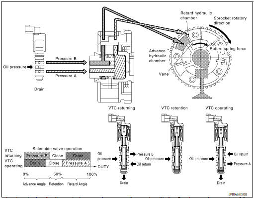
This mechanism hydraulically controls cam phases continuously with the fixed operating angle of the intake valve.
The ECM receives signals such as crankshaft position, camshaft position, engine speed, and engine coolant temperature. Then, the ECM sends ON/OFF pulse duty signals to the intake valve timing (IVT) control solenoid valve depending on driving status. This makes it possible to control the shut/open timing of the intake valve to increase engine torque in low/mid speed range and output in high-speed range.
INTAKE VALVE TIMING INTERMEDIATE LOCK CONTROL
System Diagram
System Description
The intake valve timing intermediate lock control improves the cleaning ability of exhaust gas at cold starting by fixing the camshaft sprocket (INT) with two lock keys and bringing the cam phase into intermediate phase.
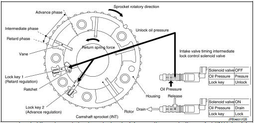
Cam phase is fixed at the intermediate phase by two lock keys in the camshaft sprocket (INT). Lock key 1 controls retard position and lock key 2 controls advance position.
ECM controls the intermediate phase lock by opening/closing the intake valve timing intermediate lock control solenoid valve to control oil pressure acting on the lock key and locking/unlocking the lock key.
Lock/Unlock Activation
When ECM activates the intake valve timing intermediate lock control solenoid valve, oil pressure generated in the oil pump is drained through the oil pressure path in the control valve. Since oil pressure is not acted on the lock key, the lock key position is fixed by the spring tension and the cam phase is fixed at the intermediate phase.
When ECM deactivates the intake valve timing intermediate lock control solenoid valve, unlocking oil pressure acts on each lock key. Lock key 1 is not released because it is under load due to sprocket rotational force. For this reason, lock key 2 is released first by being pushed up by unlocking oil pressure. When lock key 2 is released, some clearance is formed between lock key 1 and the rotor due to sprocket rotational force and return spring force. Accordingly, lock key 1 is pushed up by unlocking oil pressure and the intermediated phase lock is released.
When stopping the engine
When the ignition switch is turned from idle state to OFF, ECM receives an ignition switch signal from BCM via CAN communication and activates the intake valve timing intermediate lock control solenoid valve and drains oil pressure acting on the lock key before activating the intake valve timing control solenoid valve and operating the cam phase toward the advance position.
The cam phase is fixed by the lock key when shifting to the intermediated phase and ECM performs Lock judgment to stop the engine.
When starting the engine When starting the engine by cold start, ECM judges the locked/unlocked state when ignition switch is turned ON. When judged as locked state (fixed at the intermediate phase), the intake valve timing intermediate lock control solenoid valve is activated. Since oil pressure does not act on the lock key even when the engine is started, the cam phase is fixed at the intermediate phase and the intake valve timing control is not performed.
When the engine stops without locking the cam phase at the intermediate phase due to an engine stall and the state is not judged as locked, the intake valve timing intermediate lock control solenoid valve and the intake valve timing control solenoid valve are activated and the cam phase shifts to the advanced position to be locked at the intermediate phase. Even when not locked in the intermediate lock phase due to no oil pressure or low oil pressure, a ratchet structure of the camshaft sprocket (INT) rotor allows the conversion to the intermediate phase in stages by engine vibration.
When engine coolant temperature is more than 60°C, the intake valve timing is controlled by deactivating the intake valve timing intermediate lock control solenoid valve and releasing the intermediate phase lock.
When the engine is started after warming up, ECM releases the intermediate phase lock immediately after the engine start and controls the intake valve timing.
EXHAUST VALVE TIMING CONTROL
EXHAUST VALVE TIMING CONTROL : System Description
SYSTEM DIAGRAM
SYSTEM DESCRIPTION
This mechanism hydraulically controls cam phases continuously with the fixed operating angle of the exhaust valve.
The ECM receives signals such as crankshaft position, camshaft position, engine speed, and engine oil temperature.
Then, the ECM sends ON/OFF pulse duty signals to the exhaust valve timing (EVT) control solenoid valve depending on driving status. This makes it possible to control the shut/open timing of the exhaust valve to increase engine torque and output in a range of high engine speed.
INTAKE MANIFOLD RUNNER CONTROL
INTAKE MANIFOLD RUNNER CONTROL : System Description
SYSTEM DIAGRAM
SYSTEM DESCRIPTION
Intake manifold runner control valve has a valve portion in the intake passage of each cylinder.
While idling and during low engine coolant temperature, the intake manifold runner control valve closes. Thus the velocity of the air in the intake passage increases, promoting the vaporization of the fuel and producing a intake manifold runner in the combustion chamber.
Because of this operation, this system tends to increase the burning speed of the gas mixture, improve exhaust emission, and increase the stability in running conditions.
Also, except when idling and during low engine coolant temperature, this system opens the intake manifold runner control valve.
In this condition, this system tends to increase power by improving intake efficiency via reduction of intake flow resistance.
The intake manifold runner control valve is operated by the ECM.
ENGINE PROTECTION CONTROL AT LOW ENGINE OIL PRES
ENGINE PROTECTION CONTROL AT LOW ENGINE OIL PRESSURE : System Description
SYSTEM DIAGRAM
SYSTEM DESCRIPTION
- The engine protection control at low engine oil pressure warns the driver of a decrease in engine oil pressure by the engine oil pressure warning lamp a before the engine becomes damaged.
- When detecting a decrease in engine oil pressure at an engine speed less than 1,000 rpm, ECM transmits an engine oil pressure warning lamp signal to the combination meter.The combination meter turns ON the engine oil pressure warning lamp, according to the signal.
| Decrease in engine oil pressure | Engine speed | Combination meter | Fuel cut |
| Engine oil pressure warning lamp | |||
| Detection | Less than 1,000 rpm | ON* | ON |
| 1,000 rpm or more | ON | YES |
*: When detecting a normal engine oil pressure, ECM turns OFF the engine oil pressure warning lamp.
AIR CONDITIONING CUT CONTROL
AIR CONDITIONING CUT CONTROL : System Description
SYSTEM DIAGRAM
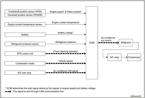
SYSTEM DESCRIPTION
This system improves engine operation when the air conditioner is used.
Under the following conditions, the air conditioner is turned off.
- When cranking the engine.
- At high engine speeds.
- When the engine coolant temperature becomes excessively high.
- When operating power steering during low engine speed or low vehicle speed.
- When engine speed is excessively low.
- When refrigerant pressure is excessively low or high.
POWER GENERATION VOLTAGE VARIABLE CONTROL SYSTEM
POWER GENERATION VOLTAGE VARIABLE CONTROL SYSTEM : System Description
DESCRIPTION
ECM transmits a target power generation voltage signal received from IPDM E/R to the generator via LIN communication.
The generator includes a self-diagnosis function and transmits a diagnosis signal to ECM via LIN communication when detecting a malfunction. When ECM receives a diagnosis signal, ECM detects DTC and transmits a charge warning lamp request signal to the combination meter to turn ON the charge warning lamp.
COOLING FAN CONTROL
COOLING FAN CONTROL : System Description
SYSTEM DIAGRAM
SYSTEM DESCRIPTION
ECM controls cooling fan speed corresponding to vehicle speed, engine coolant temperature, refrigerant pressure, air conditioner ON signal. Then control system has 3-step control [HIGH/LOW/OFF].
Cooling Fan Operation
Cooling Fan Relay Operation
The ECM controls cooling fan relays through CAN communication line.
| Cooling fan speed | Cooling fan relay | ||
| 1 | 2 | 3 | |
| Stop (OFF) | OFF | OFF | OFF |
| Low (LOW) | OFF | ON | OFF |
| High (HI) | ON | OFF | ON |
AUTOMATIC SPEED CONTROL DEVICE (ASCD)
AUTOMATIC SPEED CONTROL DEVICE (ASCD) : System Description
SYSTEM DIAGRAM
BASIC ASCD SYSTEM
Refer to Owner's Manual for ASCD operating instructions.
Automatic Speed Control Device (ASCD) allows a driver to keep vehicle at predetermined constant speed without depressing accelerator pedal. Driver can set vehicle speed in advance between approximately 40 km/ h (25 MPH) and 144 km/h (89 MPH).
ECM controls throttle angle of electric throttle control actuator to regulate engine speed.
The ASCD operation status is indicated by two indicators (CRUISE and SET on the information display) on the combination meter. If any malfunction occurs in ASCD system, SET indicator blinks and ASCD control is deactivated.
NOTE: Always drive vehicle in safe manner according to traffic conditions and obey all traffic laws.
SET OPERATION
Press MAIN switch. (CRUISE is indicated on the information display.) When vehicle speed reaches a desired speed between approximately 40 km/h (25 MPH) and 144 km/h (89 MPH), press SET/COAST switch. (Then SET is indicated on the information display.)
ACCELERATE OPERATION
If the RESUME/ACCELERATE switch is pressed during cruise control driving, increase the vehicle speed until the switch is released or vehicle speed reaches maximum speed controlled by the system.
And then ASCD will keep the new set speed.
CANCEL OPERATION
When any of following conditions exist, cruise operation will be canceled.
- CANCEL switch is pressed
- More than 2 switches at ASCD steering switch are pressed at the same time (Set speed will be cleared)
- Brake pedal is depressed
- Selector lever is changed to N, P, R position
- Vehicle speed decreased to 13 km/h (8 MPH) lower than the set speed
- TCS system is operated
When the ECM detects any of the following conditions, the ECM will cancel the cruise operation and inform the driver by blinking indicators.
- Engine coolant temperature is slightly higher than the normal operating
temperature, CRUISE indicator may
blink slowly.
When the engine coolant temperature decreases to the normal operating temperature, CRUISE indicator will stop blinking and the cruise operation will be able to work by pressing SET/COAST switch or RESUME/ ACCELERATE switch.
- Malfunction for some self-diagnoses regarding ASCD control: SET
indicator will blink quickly.
If MAIN switch is turned to OFF during ASCD is activated, all of ASCD operations will be canceled and vehicle speed memory will be erased.
COAST OPERATION
When the SET/COAST switch is pressed during cruise control driving, decrease vehicle set speed until the switch is released. And then ASCD will keep the new set speed.
RESUME OPERATION
When the RESUME/ACCELERATE switch is pressed after cancel operation other than pressing MAIN switch is performed, vehicle speed will return to last set speed. To resume vehicle set speed, vehicle condition must meet following conditions.
- Brake pedal is released
- Selector lever is in other than P and N positions
- Vehicle speed is greater than 40 km/h (25 MPH) and less than 144 km/h (89 MPH)
FUEL FILLER CAP WARNING SYSTEM
FUEL FILLER CAP WARNING SYSTEM : System Description
SYSTEM DIAGRAM
SYSTEM DESCRIPTION
The fuel filler cap warning system alerts the driver to the prevention of the fuel filler being left uncapped and malfunction occurrences after refueling, by turning ON the fuel filler cap warning display on the combination meter.
ECM judges a refueled state, based on a fuel level signal transmitted from the combination meter.
When a very small leak is detected through the EVAP leak diagnosis performed after judging the refueled state, ECM transmits a fuel filler cap warning display signal (request for display ON) to the combination meter via CAN communication.
When receiving the signal, the combination meter turns ON the fuel filler cap warning display.
CAUTION: Check fuel filler cap installation condition when the fuel filler cap warning display turns ON.
Reset Operation
The fuel filler cap warning lamp tunes OFF, according to any condition listed below:
- Reset operation is performed by operating the meter control switch on the combination meter. Refer to MWI- 18, "Switch Name and Function".
- When the reset operation is performed, the combination meter transmits a fuel filler cap warning reset signal to ECM via CAN communication. ECM transmits a fuel filler cap warning display signal (request for display OFF) to the combination meter via CAN communication. When receiving the signal, the combination meter turns OFF the fuel filler cap warning display.
- EVAP leak diagnosis result is normal.
- Fuel refilled.
- DTC erased by using CONSULT.
NOTE: MIL turns ON if a malfunction is detected in leak diagnosis results again at the trip after the fuel filler cap warning display turns ON/OFF.
WARNING/INDICATOR/CHIME LIST
WARNING/INDICATOR/CHIME LIST : Warning lamps/Indicator lamps
| Name | Arrangement/Function |
| Malfunction indicator lamp (MIL) | Regarding the function. Refer to EC-49, "WARNING/INDICATOR/CHIME LIST : Malfunction Indicator Lamp (MIL)". |
WARNING/INDICATOR/CHIME LIST : Warning/Indicator (On Information Display)
WARNING
| Name | Arrangement/Function |
| Engine oil pressure warning | Regarding the function. Refer to EC-51, "WARNING/INDICATOR/CHIME LIST : Engine Oil Pressure Warning". |
| Fuel filler cap warning | Regarding the function. Refer to EC-52, "WARNING/INDICATOR/CHIME LIST : Fuel Filler Cap Warning". |
INDICATOR/INFORMATION
| Name | Design | Function |
| 1 CRUISE indicator 2 SET indicator |
|
EC-47, "AUTOMATIC SPEED CONTROL DEVICE (ASCD) : System Description" |
WARNING/INDICATOR/CHIME LIST : Malfunction Indicator Lamp (MIL)
DESIGN/PURPOSE
When a malfunction which increases exhaust gases is detected, ECM turns ON MIL and informs the driver of the necessity of inspection and repair.
When a malfunction which causes damage to the catalyst is detected, ECM immediately blinks MIL to alert the driver.
BULB CHECK
The bulb turns ON after turning ON the ignition switch (engine stop) and turns OFF after restarting the engine.
OPERATION AT COMBINATION METER CAN COMMUNICATION CUT-OFF OR UNUSUAL SIGNAL
For the operation for CAN communication blackout in the combination meter, refer to MWI-29, "Fail-safe".
SYSTEM DIAGRAM
SIGNAL PATH
- When the lighting conditions of the malfunction indicator lamp (MIL) are satisfied, ECM transmits a malfunction indicator lamp (MIL) signal to the combination meter via CAN communication.
- The combination meter turns ON or blinks the malfunction indicator lamp (MIL), according to a signal received from ECM.
LIGHTING CONDITION
When all of the following conditions are satisfied:
- Ignition switch: ON
- DTC which influences on exhaust gasses is judged.
For DTCs that the malfunction indicator lamp turns ON and the number of DTC diagnosis trips, refer to EC-93, "DTC Index".
SHUTOFF CONDITION
When any of the following conditions is satisfied:
- Ignition switch: OFF
- Erase DTC
NOTE: For the conditions of erasing DTC, refer to EC-57, "DIAGNOSIS DESCRIPTION : DTC and Freeze Frame Data".
TIMING CHART
WARNING/INDICATOR/CHIME LIST : Engine Oil Pressure War
DESIGN/PURPOSE
When engine oil pressure is low, the engine oil pressure warning informs the driver of low oil pressure to prevent damage to the engine.
| Symbol | Message |
|
|
|
BULB CHECK
Not applicable
OPERATION AT COMBINATION METER CAN COMMUNICATION CUT-OFF OR UNUSUAL SIGNAL
For the operation for CAN communications blackout or abnormal signal reception, refer to MWI-29, "Fail-safe".
SYSTEM DIAGRAM
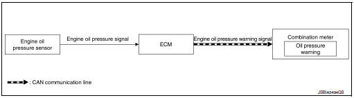
SIGNAL PATH
ECM calculates an engine oil pressure according to a signal transmitted from the engine oil pressure sensor.
After engine running when the engine oil pressure is low and at least 5 seconds, ECM transmits the engine oil pressure warning signal to combination meter via CAN communication. Then the engine oil pressure warning displays.
LIGHTING CONDITION
When all of the following conditions for at least 5 seconds are satisfied:
- Ignition switch: ON
- Engine oil pressure is less than specified value.
- Engine speed is more than 500 rpm.
SHUTOFF CONDITION
When any of the following conditions is satisfied:
- Ignition switch: OFF
- Engine oil pressure is the specified value or more.
- Engine speed is less than 500 rpm.
TIMING CHART
WARNING/INDICATOR/CHIME LIST : Fuel Filler Cap Warning
DESIGN/PURPOSE
Warn the driver that the fuel filler cap is left opened.
| Symbol | Message |
|
|
Loose Fuel Cap |
For detailes, refer to EC-48, "FUEL FILLER CAP WARNING SYSTEM : System Description".
EVAPORATIVE EMISSION SYSTEM
EVAPORATIVE EMISSION SYSTEM : System Description
SYSTEM DIAGRAM
SYSTEM DESCRIPTION
The evaporative emission system is used to reduce hydrocarbons emitted into the atmosphere from the fuel system. This reduction of hydrocarbons is accomplished by activated charcoals in the EVAP canister.
The fuel vapor in the sealed fuel tank is led into the EVAP canister which contains activated carbon and the vapor is stored there when the engine is not operating or when refueling to the fuel tank.
The vapor in the EVAP canister is purged by the air through the purge line to the intake manifold when the engine is operating. EVAP canister purge volume control solenoid valve is controlled by ECM. When the engine operates, the flow rate of vapor controlled by EVAP canister purge volume control solenoid valve is proportionally regulated as the air flow increases.
EVAP canister purge volume control solenoid valve also shuts off the vapor purge line during decelerating.
CAN COMMUNICATION
CAN COMMUNICATION : System Description
CAN (Controller Area Network) is a serial communication line for real time application. It is an on-vehicle multiplex communication line with high data communication speed and excellent error detection ability. Many electronic control units are equipped onto a vehicle, and each control unit shares information and links with other control units during operation (not independent). In CAN communication, control units are connected with 2 communication lines (CAN H line, CAN L line) allowing a high rate of information transmission with less wiring.
Each control unit transmits/receives data but selectively reads required data only.
Refer to LAN-32, "CAN COMMUNICATION SYSTEM : CAN Communication Signal Chart", about CAN communication for detail.
SPORT MODE CONTROL
SPORT MODE CONTROL : System Description
SYSTEM DIAGRAM
SYSTEM DESCRIPTION
- SPORT mode that keeps high engine revolution and provides direct feel and acceleration performance suitable for driving on winding road.
- ECM receives an SPORT mode signal from TCM via CAN communication and improves drivability by controlling the throttle movement.
- ECM transmits an SPORT mode indicator lamp signal to the combination meter via CAN communication.
NOTE: For the details of the SPORT mode, refer to DMS-6, "SPORT MODE CONTROL : System Description".
 Structure and operation
Positive Crankcase Ventilation
This system returns blow-by gas to the intake manifold.
The positive crankcase ventilation (PCV) valve is provided to conduct crankcase
blow-by gas to the inta ...
 Operation
AUTOMATIC SPEED CONTROL DEVICE (ASCD)
AUTOMATIC SPEED CONTROL DEVICE (ASCD) : Switch Name and Function
SWITCHES AND INDICATORS
A On the combination meter
B On the steering wheel
1 CRUISE ind ...
Other materials:
Precaution
Precaution for Supplemental Restraint System (SRS) "AIR BAG" and "SEAT
BELT
PRE-TENSIONER"
The Supplemental Restraint System such as “AIR BAG” and “SEAT BELT PRE-TENSIONER”,
used along
with a front seat belt, helps to reduce the risk or severity of injury to the
...
Unit disassembly and assembly
REAR DRIVE SHAFT
Exploded View
DISASSEMBLY
Circular clip
Dust shield
Slide joint housing
Snap ring
Spider assembly
Boot band
Boot
Shaft
Circular clip
Joint sub-assembly
Sensor rotor
: Wheel side
Disassembly and Assembly
DISASSEMBLY
Final Dri ...
DTC/circuit diagnosis
DOOR MIRROR REMOTE CONTROL SWITCH (MIRROR SWITCH/
CHANGEOVER SWITCH)
Component Inspection
1.CHECK MIRROR SWITCH & CHANGEOVER SWITCH
Turn ignition switch OFF.
Disconnect door mirror remote control switch connector.
Check door mirror remote control switch.
Is th ...
