Nissan Rogue Service Manual: Sample/Wiring Diagram -Example-
Each section includes wiring diagrams.
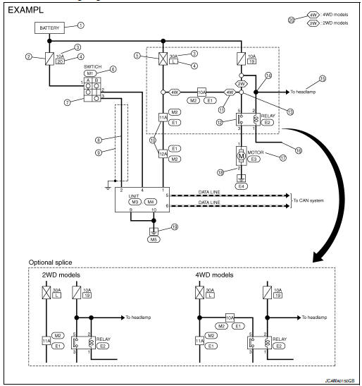
Description
| Number | Item | Description |
| 1 | Power supply |
|
| 2 | Fuse |
|
| 3 | Current rating of fusible link/fuse |
|
| 4 | Number of fusible link/ fuse |
|
| 5 | Fusible link |
|
| 6 | Connector number |
|
| 7 | Switch |
|
| 8 | Circuit (Wiring) |
|
| 9 | Shielded line |
|
| 10 | Connectors |
|
| 11 | Option abbreviation |
|
| 12 | Relay |
|
| 13 | Optional splice |
|
| 14 | Splice |
|
| 15 | System branch |
|
| 16 | Page crossing |
|
| 17 | Component name |
|
| 18 | Terminal number |
|
| 19 | Ground (GND) |
|
| 20 | Explanation of option description |
|
 ”.
”. ” means the splice.
SWITCH POSITIONS
Switches are shown in wiring diagrams as if the vehicle is in the “normal” condition.
A vehicle is in the “normal” condition when:
- ignition switch is “OFF”
- doors, hood and trunk lid/back door are closed
- pedals are not depressed
- parking brake is released
MULTIPLE SWITCH
The continuity of multiple switch is described in two ways as shown below.
- The switch chart is used in schematic diagrams.
- The switch diagram is used in wiring diagrams.
 Connector Symbols
Most of connector symbols in wiring diagrams are shown from the terminal
side.
Connector symbols shown from the terminal side are enclosed by
a single line and followed by the direction ...
 Connector Information
HOW TO USE CONNECTOR INFORMATION
Description
Number
Item
Description
1
Connector number
Alphabetic characters show to which harness the connector is
pla ...
Other materials:
System description
DESCRIPTION
Engine Cooling System
Thermostat
Water outlet
Cylinder block (Thermostat housing)
Water inlet
Radiator
Water pump
Cylinder block
Cylinder head
Open
Closed
To electric throttle control actuator
To oil cooler
...
Front disc brake
Brake Burnishing
CAUTION:
Burnish contact surfaces between brake pads and disc brake
rotor according to the following procedure
after refinishing the disc brake rotor, replacing brake pads or if a soft
pedal occurs at very low
mileage.
Be careful of vehicle speed. Brakes ...
System description
DESCRIPTION
Engine Lubrication System
Camshaft (INT)
Chain tensioner
Main gallery
Oil pan
Oil cooler
Balancer unit
Oil pan oil gallery
Oil filter (with relief valve)
Oil Strainer
Oil pump
Timing chain and balancer unit timing
chain ...
