Nissan Rogue Service Manual: Connector Information
HOW TO USE CONNECTOR INFORMATION
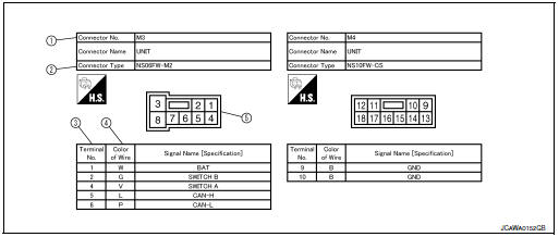
Description
| Number | Item | Description |
| 1 | Connector number |
|
| 2 | Connector type |
|
| 3 | Terminal number |
|
| 4 | Wire color |
|
| B = Black W = White R = Red G = Green L = Blue Y = Yellow LG = Light Green BG = Beige BR = Brown LA = Lavender OR or O = Orange P = Pink PU or V (Violet) = Purple GY or GR = Gray SB = Sky Blue CH = Dark Brown DG = Dark Green |
||
|
||
| 5 | Connector |
|
 Sample/Wiring Diagram -Example-
Each section includes wiring diagrams.
Description
Number
Item
Description
1
Power supply
This means the power supply of fusible link or fuse.
...
 Abbreviations
Abbreviation List
The following ABBREVIATIONS are used:
...
Other materials:
Steering angle sensor
Exploded View
Combination switch
Steering angle sensor
Spiral cable
Removal and Installation
Removal and Installation
Remove the spiral cable. Refer to SR-15, "Exploded View".
Remove screws (A) and then remove steering angle sensor (1).
INSTALLATI ...
Headlining
Exploded View
WITHOUT MOONROOF
Map lamp assembly bracket
Headlining
Assist grip (without coat hanger)
Map lamp assembly
Sun visor holder (LH/RH)
Sun visor (RH)
Sun visor cover
Sun visor (LH)
Headlining cover
Assist grip (with coat hanger ...
Foreword
This manual contains maintenance and repair procedure for the 2014
NISSAN ROGUE.
In order to assure your safety and the efficient functioning of the vehicle,
this manual should be read thoroughly. It is especially important that the
PRECAUTIONS in the GI section be completely understood before ...
