Nissan Rogue Service Manual: Foreword
This manual contains maintenance and repair procedure for the 2014 NISSAN ROGUE.
In order to assure your safety and the efficient functioning of the vehicle, this manual should be read thoroughly. It is especially important that the PRECAUTIONS in the GI section be completely understood before starting any repair task.
All information in this manual is based on the latest product information at the time of publication. The right is reserved to make changes in specifications and methods at any time without notice.
IMPORTANT SAFETY NOTICE
The proper performance of service is essential for both the safety of the technician and the efficient functioning of the vehicle.
The service methods in this Service Manual are described in such a manner that the service may be performed safely and accurately.
Service varies with the procedures used, the skills of the technician and the tools and parts available. Accordingly, anyone using service procedures, tools or parts which are not specifically recommended by NISSAN must first be completely satisfied that neither personal safety nor the vehicle’s safety will be jeopardized by the service method selected.
QUICK REFERENCE CHART: ROGUE
Engine Tune-up Data
GENERAL SPECIFICATIONS
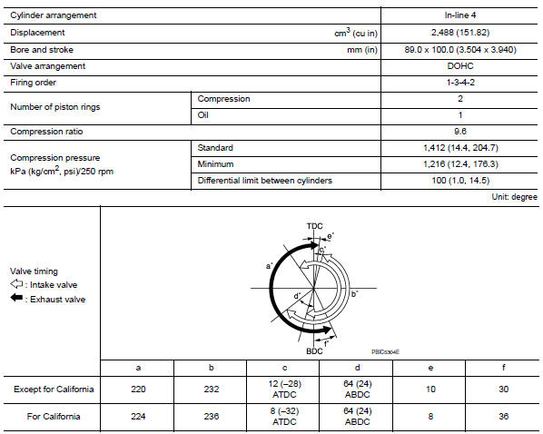
( ): Valve timing control “ON”
Drive belt
DRIVE BELT

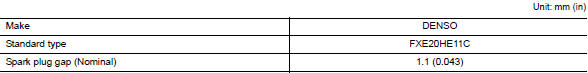
Spark Plug
SPARK PLUG
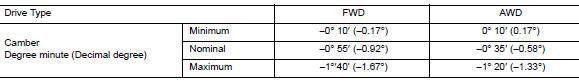
Front Wheel Alignment (Unladen*1)
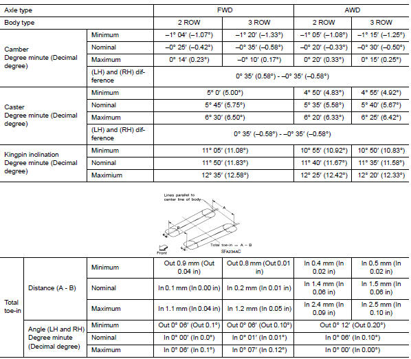
*1: Fuel, engine coolant, and lubricants are full. Spare tire, jack, hand tools, and mats are in designated positions.
Rear Wheel Alignment (Unladen*1)
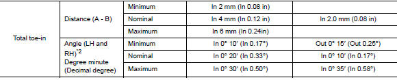
*1: Fuel, engine coolant, and lubricants are full. Spare tire, jack, hand
tools, and mats are in designated positions.
*2: Since an adjustment mechanism is not included, the value of the left and
right wheels must be used as the standard value.
Wheelarch Height (Unladen*)
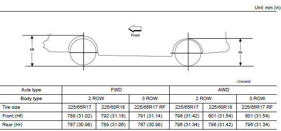
*: Fuel, engine coolant, and lubricants are full. Spare tire, jack, hand tools, and mats are in designated positions.
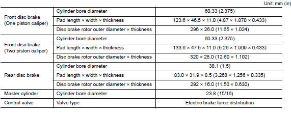
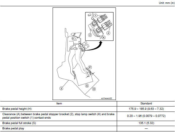
Brake Specifications
Brake Pedal
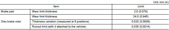
Front Disc Brake
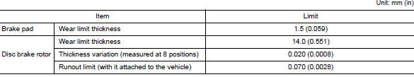
Rear Disc Brake
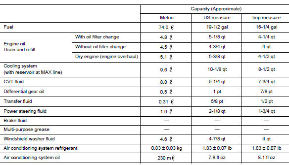
Fluids and Lubricants
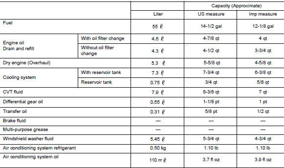
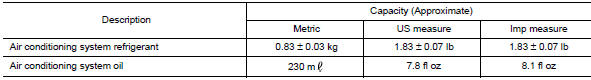
FOR MEXICO : Fluids and Lubricants
 Nissan Rogue Service Manual
Ôªø ...

Other materials:
Component parts
Component Parts Location
Instrument lower panel LH
No.
Component
Function
1
Combination meter
The combination meter transmittes the following signal via CAN
communications
to the TCM.
SPORT mode switch signal
...
Tow truck towing
CAUTION:
All applicable state or Provincial (in Canada) laws and local
laws regarding the towing operation
must be obeyed.
It is necessary to use proper towing equipment to avoid
possible damage to the vehicle during towing
operation. Towing is in accordance with Towing P ...
General maintenance
Explanation of General Maintenance
General maintenance includes those items which should be checked during the
normal day-to-day operation
of the vehicle. They are essential if the vehicle is to continue operating
properly. The owners can perform the
checks and inspections themselves or have ...
